Cisco 7609-S Installation Guide - Page 86
Removing and Replacing the Fan Assembly
 |
View all Cisco 7609-S manuals
Add to My Manuals
Save this manual to your list of manuals |
Page 86 highlights
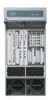
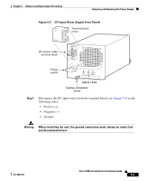
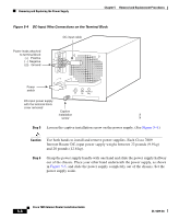
Removing and Replacing the Fan Assembly Chapter 5 Removal and Replacement Procedures Step 9 After ensuring that all wire connections are secure, reinstall the terminal block cover. Caution To prevent a short circuit or shock hazard after wiring the DC-input power supply, reinstall the terminal block cover. Caution In a system with dual power supplies, connect each power supply to a separate input line. In case of a line failure, the second source will most likely still be available. Step 10 Step 11 Step 12 Remove the tape from the circuit breaker switch handle and restore power by moving the circuit breaker switch handle to the On (|) position. Turn the power switch to the On (|) position on the power supply. Turning the power switch on also engages a pawl that locks the power supply in the chassis. Verify power supply operation by checking that the power supply front panel LEDs are in the following states: • INPUT OK LED is green • FAN OK LED is green • OUTPUT FAIL LED is not lit If the LEDs indicate a power problem, see the "Identifying Startup Problems" section on page 4-3. Removing and Replacing the Fan Assembly This section describes how to remove and replace fan assemblies for the Cisco 7609 Internet Router. A flat-blade or number 2 Phillips-head screwdriver is required to perform this procedure. 5-12 Cisco 7609 Internet Router Installation Guide OL-5079-04
-
 1
1 -
2
-
3
-
4
-
5
-
6
-
7
-
8
-
9
-
10
-
11
-
12
-
13
-
14
-
15
-
16
-
17
-
18
-
19
-
20
-
21
-
22
-
23
-
24
-
25
-
26
-
27
-
28
-
29
-
30
-
31
-
32
-
33
-
34
-
35
-
36
-
37
-
38
-
39
-
40
-
41
-
42
-
43
-
44
-
45
-
46
-
47
-
48
-
49
-
50
-
51
-
52
-
53
-
54
-
55
-
56
-
57
-
58
-
59
-
60
-
61
-
62
-
63
-
64
-
65
-
66
-
67
-
68
-
69
-
70
-
71
-
72
-
73
-
74
-
75
-
76
-
77
-
78
-
79
-
80
-
 81
81 -
 82
82 -
 83
83 -
 84
84 -
 85
85 -
 86
86 -
 87
87 -
 88
88 -
 89
89 -
 90
90 -
 91
91 -
92
-
93
-
94
-
95
-
96
-
97
-
98
-
99
-
100
-
101
-
102
-
103
-
104
-
105
-
106
-
107
-
108
-
109
-
110
-
111
-
112
-
113
-
114
-
115
-
116
-
117
-
118
-
119
-
120
 |
 |
