Cisco 7609-S Installation Guide - Page 80
Removing a DC-Input Power Supply
 |
View all Cisco 7609-S manuals
Add to My Manuals
Save this manual to your list of manuals |
Page 80 highlights
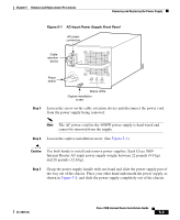
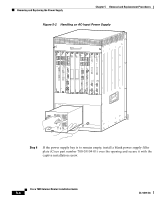
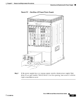
Removing and Replacing the Power Supply Chapter 5 Removal and Replacement Procedures Step 8 Step 9 Turn the power switch to the On (|) position on the power supply. Switching the power switch to On also engages a pawl that locks the power supply in the bay. Verify power supply operation by checking that the power supply front panel LEDs are in the following states: • INPUT OK LED is green • FAN OK LED is green • OUTPUT FAIL LED is not lit If the LEDs indicate a power problem, see the "Identifying Startup Problems" section on page 4-3 for troubleshooting information. Removing a DC-Input Power Supply Warning Before performing any of the following procedures, ensure that power is removed from the DC circuit. To ensure that all power is OFF, locate the circuit breaker on the panel board that services the DC circuit, switch the circuit breaker to the OFF position, and tape the switch handle of the circuit breaker in the OFF position. Warning Voltage is present on the backplane when the system is operating. To reduce risk of an electric shock, keep hands and fingers out of the power supply bays and backplane areas. Follow these steps to remove a DC-input power supply: Step 1 Step 2 Step 3 Verify that power is off to the DC circuit on the power supply you are removing. Turn the power switch to the Off (0) position on the power supply you are removing. (See Figure 5-3.) Turning the power switch off also disengages a pawl that unlocks the power supply from the chassis. Remove the two screws securing the terminal block cover, and slide the cover off the terminal block. (See Figure 5-3.) Cisco 7609 Internet Router Installation Guide 5-6 OL-5079-04
-
 1
1 -
2
-
3
-
4
-
5
-
6
-
7
-
8
-
9
-
10
-
11
-
12
-
13
-
14
-
15
-
16
-
17
-
18
-
19
-
20
-
21
-
22
-
23
-
24
-
25
-
26
-
27
-
28
-
29
-
30
-
31
-
32
-
33
-
34
-
35
-
36
-
37
-
38
-
39
-
40
-
41
-
42
-
43
-
44
-
45
-
46
-
47
-
48
-
49
-
50
-
51
-
52
-
53
-
54
-
55
-
56
-
57
-
58
-
59
-
60
-
61
-
62
-
63
-
64
-
65
-
66
-
67
-
68
-
69
-
70
-
71
-
72
-
73
-
74
-
 75
75 -
 76
76 -
 77
77 -
 78
78 -
 79
79 -
 80
80 -
 81
81 -
 82
82 -
 83
83 -
 84
84 -
 85
85 -
86
-
87
-
88
-
89
-
90
-
91
-
92
-
93
-
94
-
95
-
96
-
97
-
98
-
99
-
100
-
101
-
102
-
103
-
104
-
105
-
106
-
107
-
108
-
109
-
110
-
111
-
112
-
113
-
114
-
115
-
116
-
117
-
118
-
119
-
120
 |
 |
