Cisco 7609-S Installation Guide - Page 81
DC-Input Power Supply Front Panels
 |
View all Cisco 7609-S manuals
Add to My Manuals
Save this manual to your list of manuals |
Page 81 highlights
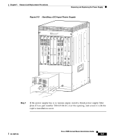
Chapter 5 Removal and Replacement Procedures Removing and Replacing the Power Supply Figure 5-3 DC-Input Power Supply Front Panels Terminal block cover DC power cable terminal block 16028 Power switch I 0 INPUT FAN OUTPUT OK OK FAIL Status LEDs Captive installation screw Step 4 Disconnect the DC-input wires from the terminal block (see Figure 5-4) in the following order: • Positive (+) • Negative (-) • Ground Warning When installing the unit, the ground connection must always be made first and disconnected last. OL-5079-04 Cisco 7609 Internet Router Installation Guide 5-7
-
 1
1 -
2
-
3
-
4
-
5
-
6
-
7
-
8
-
9
-
10
-
11
-
12
-
13
-
14
-
15
-
16
-
17
-
18
-
19
-
20
-
21
-
22
-
23
-
24
-
25
-
26
-
27
-
28
-
29
-
30
-
31
-
32
-
33
-
34
-
35
-
36
-
37
-
38
-
39
-
40
-
41
-
42
-
43
-
44
-
45
-
46
-
47
-
48
-
49
-
50
-
51
-
52
-
53
-
54
-
55
-
56
-
57
-
58
-
59
-
60
-
61
-
62
-
63
-
64
-
65
-
66
-
67
-
68
-
69
-
70
-
71
-
72
-
73
-
74
-
75
-
 76
76 -
 77
77 -
 78
78 -
 79
79 -
 80
80 -
 81
81 -
 82
82 -
 83
83 -
 84
84 -
 85
85 -
 86
86 -
87
-
88
-
89
-
90
-
91
-
92
-
93
-
94
-
95
-
96
-
97
-
98
-
99
-
100
-
101
-
102
-
103
-
104
-
105
-
106
-
107
-
108
-
109
-
110
-
111
-
112
-
113
-
114
-
115
-
116
-
117
-
118
-
119
-
120
 |
 |

5-7
Cisco 7609 Internet Router Installation Guide
OL-5079-04
Chapter 5
Removal and Replacement Procedures
Removing and Replacing the Power Supply
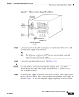
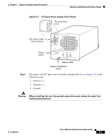
Figure 5-3
DC-Input Power Supply Front Panels
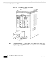
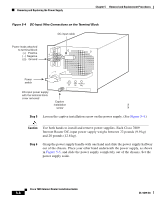
Step 4
Disconnect the DC-input wires from the terminal block (see
Figure 5-4
) in the
following order:
•
Positive (+)
•
Negative (–)
•
Ground
Warning
When installing the unit, the ground connection must always be made first
and disconnected last.
16028
Power
switch
DC power cable
terminal block
Terminal block
cover
INPUT
OK
FAN
OK
OUTPUT
FAIL
I
0
Status LEDs
Captive installation
screw