Cisco 7609-S Installation Guide - Page 82
DC-Input Wire Connections on the Terminal Block
 |
View all Cisco 7609-S manuals
Add to My Manuals
Save this manual to your list of manuals |
Page 82 highlights
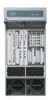
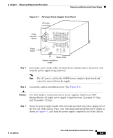
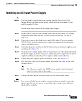
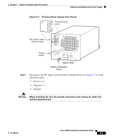
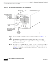
Removing and Replacing the Power Supply Chapter 5 Removal and Replacement Procedures Figure 5-4 DC-Input Wire Connections on the Terminal Block DC-input cable Power leads attached to terminal block (+) Positive ( - ) Negative ( ) Ground Power switch I 0 INPUT FAN OUTPUT OK OK FAIL DC-input power supply with the terminal block cover removed Captive installation screw 18736 Step 5 Loosen the captive installation screw on the power supply. (See Figure 5-4.) Caution Use both hands to install and remove power supplies. Each Cisco 7609 Internet Router DC-input power supply weighs between 22 pounds (9.9 kg) and 28 pounds (12.6 kg). Step 6 Grasp the power supply handle with one hand and slide the power supply halfway out of the chassis. Place your other hand underneath the power supply, as shown in Figure 5-5, and slide the power supply completely out of the chassis. Set the power supply aside. Cisco 7609 Internet Router Installation Guide 5-8 OL-5079-04
-
 1
1 -
2
-
3
-
4
-
5
-
6
-
7
-
8
-
9
-
10
-
11
-
12
-
13
-
14
-
15
-
16
-
17
-
18
-
19
-
20
-
21
-
22
-
23
-
24
-
25
-
26
-
27
-
28
-
29
-
30
-
31
-
32
-
33
-
34
-
35
-
36
-
37
-
38
-
39
-
40
-
41
-
42
-
43
-
44
-
45
-
46
-
47
-
48
-
49
-
50
-
51
-
52
-
53
-
54
-
55
-
56
-
57
-
58
-
59
-
60
-
61
-
62
-
63
-
64
-
65
-
66
-
67
-
68
-
69
-
70
-
71
-
72
-
73
-
74
-
75
-
76
-
 77
77 -
 78
78 -
 79
79 -
 80
80 -
 81
81 -
 82
82 -
 83
83 -
 84
84 -
 85
85 -
 86
86 -
 87
87 -
88
-
89
-
90
-
91
-
92
-
93
-
94
-
95
-
96
-
97
-
98
-
99
-
100
-
101
-
102
-
103
-
104
-
105
-
106
-
107
-
108
-
109
-
110
-
111
-
112
-
113
-
114
-
115
-
116
-
117
-
118
-
119
-
120
 |
 |
