Cisco 7609-S Installation Guide - Page 88
Installing the Fan Assembly
 |
View all Cisco 7609-S manuals
Add to My Manuals
Save this manual to your list of manuals |
Page 88 highlights
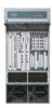
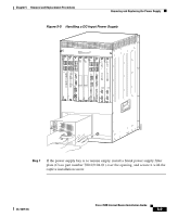
Removing and Replacing the Fan Assembly Chapter 5 Removal and Replacement Procedures Step 2 Step 3 Loosen the two captive installation screws by turning them counterclockwise. Grasp the fan assembly with both hands and pull it outward; rock it gently if necessary to unseat the power connector from the backplane. Warning When removing the fan tray, keep your hands and fingers away from the spinning fan blades. Let the fan blades completely stop before you remove the fan tray. Step 4 Pull the fan assembly clear of the chassis and place it in a safe place. Installing the Fan Assembly Perform these steps to install the new fan assembly: Step 1 Step 2 Step 3 Step 4 Hold the fan assembly with the fans facing down and the FAN STATUS LED on the left. (See Figure 5-7.) Place the fan assembly into the front chassis cavity so it rests on the chassis, and then lift the fan assembly up slightly, aligning the top and bottom chassis guides. Push the fan assembly into the chassis until the power connector seats in the backplane and the captive installation screws make contact with the chassis. Tighten the captive installation screws. 5-14 Cisco 7609 Internet Router Installation Guide OL-5079-04
-
 1
1 -
2
-
3
-
4
-
5
-
6
-
7
-
8
-
9
-
10
-
11
-
12
-
13
-
14
-
15
-
16
-
17
-
18
-
19
-
20
-
21
-
22
-
23
-
24
-
25
-
26
-
27
-
28
-
29
-
30
-
31
-
32
-
33
-
34
-
35
-
36
-
37
-
38
-
39
-
40
-
41
-
42
-
43
-
44
-
45
-
46
-
47
-
48
-
49
-
50
-
51
-
52
-
53
-
54
-
55
-
56
-
57
-
58
-
59
-
60
-
61
-
62
-
63
-
64
-
65
-
66
-
67
-
68
-
69
-
70
-
71
-
72
-
73
-
74
-
75
-
76
-
77
-
78
-
79
-
80
-
81
-
82
-
 83
83 -
 84
84 -
 85
85 -
 86
86 -
 87
87 -
 88
88 -
 89
89 -
 90
90 -
 91
91 -
 92
92 -
 93
93 -
94
-
95
-
96
-
97
-
98
-
99
-
100
-
101
-
102
-
103
-
104
-
105
-
106
-
107
-
108
-
109
-
110
-
111
-
112
-
113
-
114
-
115
-
116
-
117
-
118
-
119
-
120
 |
 |
