Cisco 7609-S Installation Guide - Page 72
Troubleshooting the Fan Assembly, Troubleshooting Modules - chassis 9 slot red system
 |
View all Cisco 7609-S manuals
Add to My Manuals
Save this manual to your list of manuals |
Page 72 highlights
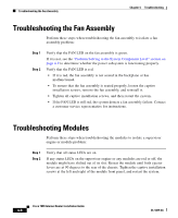
Troubleshooting the Fan Assembly Chapter 4 Troubleshooting Troubleshooting the Fan Assembly Perform these steps when troubleshooting the fan assembly to isolate a fan assembly problem: Step 1 Step 2 Verify that the FAN LED on the fan assembly is green. If it is not, see the "Problem Solving to the System Component Level" section on page 4-2 to determine whether the power subsystem is functioning properly. Verify that the FAN LED is red. • If it is red, the fan assembly is not seated in the backplane or has malfunctioned. • To ensure that the fan assembly is seated properly, loosen the captive installation screws, remove the fan assembly, and reinstall it. • Tighten all captive installation screws, and then restart the system. • If the FAN LED is still red, the system detects a fan assembly failure. Contact a customer service representative for instructions. Troubleshooting Modules Perform these steps when troubleshooting the modules to isolate a supervisor engine or module problem: Step 1 Step 2 Verify that all status LEDs are on. If any status LEDs on the supervisor engine or any modules are red or off, the module might have shifted out of its slot. Reseat the module until both ejector levers are at 90 degrees to the rear of the chassis. Tighten the captive installation screws at the left and right of the module front panel, and restart the system. Cisco 7609 Internet Router Installation Guide 4-6 OL-5079-04
-
 1
1 -
2
-
3
-
4
-
5
-
6
-
7
-
8
-
9
-
10
-
11
-
12
-
13
-
14
-
15
-
16
-
17
-
18
-
19
-
20
-
21
-
22
-
23
-
24
-
25
-
26
-
27
-
28
-
29
-
30
-
31
-
32
-
33
-
34
-
35
-
36
-
37
-
38
-
39
-
40
-
41
-
42
-
43
-
44
-
45
-
46
-
47
-
48
-
49
-
50
-
51
-
52
-
53
-
54
-
55
-
56
-
57
-
58
-
59
-
60
-
61
-
62
-
63
-
64
-
65
-
66
-
 67
67 -
 68
68 -
 69
69 -
 70
70 -
 71
71 -
 72
72 -
 73
73 -
 74
74 -
 75
75 -
 76
76 -
 77
77 -
78
-
79
-
80
-
81
-
82
-
83
-
84
-
85
-
86
-
87
-
88
-
89
-
90
-
91
-
92
-
93
-
94
-
95
-
96
-
97
-
98
-
99
-
100
-
101
-
102
-
103
-
104
-
105
-
106
-
107
-
108
-
109
-
110
-
111
-
112
-
113
-
114
-
115
-
116
-
117
-
118
-
119
-
120
 |
 |
