Cisco AIR-AP1210 Hardware Installation Guide - Page 18
Hardware Features, Dual-Radio Operation, Ethernet Port, Console Port - power injector
 |
UPC - 746320804330
View all Cisco AIR-AP1210 manuals
Add to My Manuals
Save this manual to your list of manuals |
Page 18 highlights
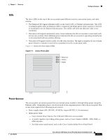
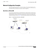
Hardware Features Chapter 1 Overview Hardware Features This section describes access point features. Refer to Appendix C, "Access Point Specifications," for a list of access point specifications. Key hardware features of the 1200 series access point include: • Dual-Radio Operation, page 1-2 • Ethernet Port, page 1-2 • Console Port, page 1-2 • LEDs, page 1-3 • Power Sources, page 1-3 • UL 2043 Certification, page 1-4 • Anti-Theft Features, page 1-4 Dual-Radio Operation The 1200 series access point can be initially configured at the factory for single- or dual-radio operation. You can also upgrade an access point configured for single-radio operation to support dual-radio operation using a 5-GHz radio module or a 2.4-GHz mini-PCI radio card. The 2.4-GHz mini-PCI radio card connects to an internal mini-PCI slot. The 5-GHz radio module connects to the access point's modified card bus connector. The module incorporates an Unlicensed National Information Infrastructure (UNII) radio transceiver operating in two of the UNII 5-GHz frequency bands and supporting up to 8 channels. The module contains dual integrated omnidirectional antennas and directional patch antennas for diversity operation. The 2.4-GHz radio is called Radio 0 and the 5-GHz radio is called Radio 1. Ethernet Port The auto-sensing Ethernet port accepts an RJ-45 connector, linking the access point to your 10BASE-T or 100BASE-T Ethernet LAN. The access point can receive power through the Ethernet cable from a power injector, switch, or power patch panel. The Ethernet MAC address is printed on the label on the back of the access point. Console Port The console port provides access to the access point's command-line interface (CLI) using a terminal emulator program. Use an RJ-45 to DB-9 serial cable to connect your computer's COM port to the access point's serial console port. (Refer to Appendix E, "Console Cable Pinouts," for a description of the console port pinouts.) Assign the following port settings to a terminal emulator to open the management system pages: 9600 baud, 8 data bits, No parity, 1 stop bit and no flow control. Cisco Aironet 1200 Series Access Point Hardware Installation Guide 1-2 OL-4310-01
-
 1
1 -
2
-
3
-
4
-
5
-
6
-
7
-
8
-
9
-
10
-
11
-
12
-
 13
13 -
 14
14 -
 15
15 -
 16
16 -
 17
17 -
 18
18 -
 19
19 -
 20
20 -
 21
21 -
 22
22 -
 23
23 -
24
-
25
-
26
-
27
-
28
-
29
-
30
-
31
-
32
-
33
-
34
-
35
-
36
-
37
-
38
-
39
-
40
-
41
-
42
-
43
-
44
-
45
-
46
-
47
-
48
-
49
-
50
-
51
-
52
-
53
-
54
-
55
-
56
-
57
-
58
-
59
-
60
-
61
-
62
-
63
-
64
-
65
-
66
-
67
-
68
-
69
-
70
-
71
-
72
-
73
-
74
-
75
-
76
-
77
-
78
-
79
-
80
-
81
-
82
-
83
-
84
-
85
-
86
-
87
-
88
-
89
-
90
-
91
-
92
-
93
-
94
-
95
-
96
-
97
-
98
-
99
-
100
-
101
-
102
-
103
-
104
-
105
-
106
-
107
-
108
-
109
-
110
-
111
-
112
-
113
-
114
-
115
-
116
-
117
-
118
-
119
-
120
-
121
-
122
-
123
-
124
-
125
-
126
-
127
-
128
 |
 |