Cisco AIR-AP1220B-A-K9 Hardware Installation Guide - Page 16
Antenna Connectors, 2.4-GHz Radio, Ethernet and Console Ports, Ethernet Port, Console Port - power injector
 |
UPC - 746320719191
View all Cisco AIR-AP1220B-A-K9 manuals
Add to My Manuals
Save this manual to your list of manuals |
Page 16 highlights
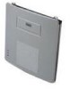
Key Features Chapter 1 Overview Antenna Connectors The access point supports two antenna connectors on the back of the unit for the 2.4-GHz radio. The 5-GHz radio supports only integrated antennas. 2.4-GHz Radio The access point provides two reverse-polarity TNC (R-TNC) connectors that you can use to connect a single antenna or dual diversity antennas to provide coverage for your wireless LAN area. Diversity coverage helps maintain a clear radio signal between the access point and wireless client devices. Just as you can improve signal clarity on your car radio at a stoplight by creeping ahead a few inches, the access point can improve signal quality by choosing the antenna that is receiving the best signal from a client device. Ethernet and Console Ports Ethernet Port Console Port The Ethernet port accepts an RJ-45 connector, linking the access point to your 10BASE-T or 100BASE-T Ethernet LAN. The access point can receive power through the Ethernet cable from a switch with inline power, from a power patch panel, or from the access point's 1200 series power injector. The console port provides access to the access point's management system using a terminal emulator program. Use an RJ-45 to DB-9 serial cable (refer to Appendix C, "Console Cable Pinouts") to connect your computer's COM port to the access point's serial console port. Assign the following port settings to a terminal emulator to open the management system pages: 9600 baud, 8 data bits, No parity, 1 stop bit and no flow control. Metal Enclosure The access point uses a metal enclosure having adequate fire resistance and low smoke-producing characteristics suitable for operation in a building's environmental air space in accordance with Section 300-22(c) of the NEC, such as above suspended ceilings. The access point also supports an industrial temperature operating range (refer to Access Point Specifications, page 1-10). Note If you plan to mount the access point in environmental air space using a 5-GHz radio, Cisco recommends that you mount the access point horizontally with its antennas pointing down. Doing so results in the access point complying with regulatory requirements for environmental air space with the 5-GHz radio installed. Cisco Aironet 1200 Series Access Point Hardware Installation Guide 1-4 OL-2155-02
-
 1
1 -
2
-
3
-
4
-
5
-
6
-
7
-
8
-
9
-
10
-
 11
11 -
 12
12 -
 13
13 -
 14
14 -
 15
15 -
 16
16 -
 17
17 -
 18
18 -
 19
19 -
 20
20 -
 21
21 -
22
-
23
-
24
-
25
-
26
-
27
-
28
-
29
-
30
-
31
-
32
-
33
-
34
-
35
-
36
-
37
-
38
-
39
-
40
-
41
-
42
-
43
-
44
-
45
-
46
-
47
-
48
-
49
-
50
-
51
-
52
-
53
-
54
-
55
-
56
-
57
-
58
-
59
-
60
-
61
-
62
-
63
-
64
-
65
-
66
-
67
-
68
-
69
-
70
-
71
-
72
-
73
-
74
-
75
-
76
-
77
-
78
-
79
-
80
-
81
-
82
-
83
-
84
-
85
-
86
-
87
-
88
-
89
-
90
-
91
-
92
-
93
-
94
-
95
-
96
-
97
-
98
-
99
-
100
-
101
-
102
-
103
-
104
-
105
-
106
-
107
-
108
-
109
-
110
 |
 |