Cisco AIR-AP1220B-A-K9 Hardware Installation Guide - Page 17
Indicators, Indicators on the 1200 Series Access Point - aironet wireless access point
 |
UPC - 746320719191
View all Cisco AIR-AP1220B-A-K9 manuals
Add to My Manuals
Save this manual to your list of manuals |
Page 17 highlights
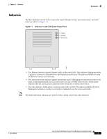
Chapter 1 Overview Key Features Indicators The three indicators on top of the access point report Ethernet activity, association status, and radio activity as shown in Figure 1-1. Figure 1-1 Indicators on the 1200 Series Access Point Radio Status Ethernet 74046 • The Ethernet indicator signals Ethernet traffic on the wired LAN. This indicator blinks green when a packet is received or transmitted over the Ethernet infrastructure. The indicator blinks red when the Ethernet cable is not connected. • The association status indicator signals operational status. Blinking green indicates that the access point is operating normally but is not associated with any wireless client devices. Steady green indicates that the access point is associated with at least one wireless client device. • The radio indicator blinks green to indicate radio traffic activity. The light is normally off, but it blinks green whenever a packet is received or transmitted over the access point radio. Note The Radio and Status indicators are used for both 2.4-GHz and 5-GHz radio operation. OL-2155-02 Cisco Aironet 1200 Series Access Point Hardware Installation Guide 1-5
-
 1
1 -
2
-
3
-
4
-
5
-
6
-
7
-
8
-
9
-
10
-
11
-
 12
12 -
 13
13 -
 14
14 -
 15
15 -
 16
16 -
 17
17 -
 18
18 -
 19
19 -
 20
20 -
 21
21 -
 22
22 -
23
-
24
-
25
-
26
-
27
-
28
-
29
-
30
-
31
-
32
-
33
-
34
-
35
-
36
-
37
-
38
-
39
-
40
-
41
-
42
-
43
-
44
-
45
-
46
-
47
-
48
-
49
-
50
-
51
-
52
-
53
-
54
-
55
-
56
-
57
-
58
-
59
-
60
-
61
-
62
-
63
-
64
-
65
-
66
-
67
-
68
-
69
-
70
-
71
-
72
-
73
-
74
-
75
-
76
-
77
-
78
-
79
-
80
-
81
-
82
-
83
-
84
-
85
-
86
-
87
-
88
-
89
-
90
-
91
-
92
-
93
-
94
-
95
-
96
-
97
-
98
-
99
-
100
-
101
-
102
-
103
-
104
-
105
-
106
-
107
-
108
-
109
-
110
 |
 |
