Cisco AIR-AP1220B-A-K9 Hardware Installation Guide - Page 22
Access Point Specifications - weight
 |
UPC - 746320719191
View all Cisco AIR-AP1220B-A-K9 manuals
Add to My Manuals
Save this manual to your list of manuals |
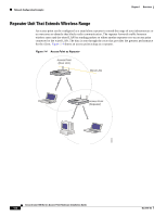
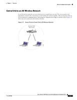
Page 22 highlights
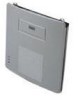
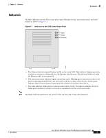
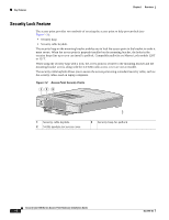
Access Point Specifications Chapter 1 Overview Access Point Specifications The access point specifications are listed in Table 1-1. Table 1-1 Access Point Specifications Category Access Point with 2.4-GHz Radio Access Point with 5-GHz Radio Module Size 6.56 in. W x 7.23 in. D x 1.66 in. H With the 5-GHz antenna in the patch position: 16.67 cm W x 18.36 cm D x 4.22 cm H 6.56 in. W x 8.04 in. D x 2.21 in. H 16.67 cm W x 20.42 cm D x 5.61 Status Indicators Three indicators on the top panel: Ethernet traffic, status, and radio traffic Connectors Back panel (left to right): reverse-TNC antenna connector; power connector (for plug-in AC power module); RJ-45 connector for 10BASE-T or 100BASE-T Ethernet connections; upside down RJ-45 connector for serial connections; reverse-TNC antenna connector. Front Panel: Card Bus connector used for the 5-GHz radio module. Input Voltage 48 VDC nominal. Operational up to 60 VDC. Voltage higher than 60 VDC can damage the unit. Input Current With 2.4 GHz radio: 125 mA (typical) With 5-GHz radio: 165 mA (typical) With 2.4-GHz and 5-GHz radios 225 mA (typical) The access point is capable of drawing 380 mA depending upon the current radios and future radios installed in the unit. Operating Temperature Access point: -4 to 131oF (-20 to 55oC) Access point (with 2.4-GHz and 5-GHz radio): -4 to 122oF (-20 to 50oC) Storage Temperature 1200 series power injector: 32 to 104oF (0 to 40oC) -40 to 185oF (-40 to 85oC) 1200 series power injector: 32 to 104oF (0 to 40oC) -40 to 185oF (-40 to 85oC) Weight Without mounting bracket: 1.6 lbs (0.73 kg) with 2.4-GHz radio module Without mounting bracket: 1.87 lbs (0.85 kg) with 5-Ghz radio module 1.97 lbs (0.89 kg) with 5-GHz radio module and 2.4-GHz radio Power Output 100, 50, 30, 20, 5, or 1 mW (Depending on the regulatory domain in which the access point is installed) 40 mW (16 dBm) 20 mW (13 dBm) 10 mW (10 dBm) 5 mW (7 dBm) Note These values are based on the FCC peak measurement method as defined in FCC 15.407 (A)(4) Frequency 2.400 to 2.497 GHz (Depending on the regulatory domain in which the access point is installed) UNII 1-5.15 to 5.25 GH UNII 2-5.25 to 5.35 GHz (Depending on the regulatory domain in which the access point is installed) 1-10 Cisco Aironet 1200 Series Access Point Hardware Installation Guide OL-2155-02
-
 1
1 -
2
-
3
-
4
-
5
-
6
-
7
-
8
-
9
-
10
-
11
-
12
-
13
-
14
-
15
-
16
-
 17
17 -
 18
18 -
 19
19 -
 20
20 -
 21
21 -
 22
22 -
 23
23 -
 24
24 -
 25
25 -
 26
26 -
 27
27 -
28
-
29
-
30
-
31
-
32
-
33
-
34
-
35
-
36
-
37
-
38
-
39
-
40
-
41
-
42
-
43
-
44
-
45
-
46
-
47
-
48
-
49
-
50
-
51
-
52
-
53
-
54
-
55
-
56
-
57
-
58
-
59
-
60
-
61
-
62
-
63
-
64
-
65
-
66
-
67
-
68
-
69
-
70
-
71
-
72
-
73
-
74
-
75
-
76
-
77
-
78
-
79
-
80
-
81
-
82
-
83
-
84
-
85
-
86
-
87
-
88
-
89
-
90
-
91
-
92
-
93
-
94
-
95
-
96
-
97
-
98
-
99
-
100
-
101
-
102
-
103
-
104
-
105
-
106
-
107
-
108
-
109
-
110
 |
 |
