Cisco CP-7937G Administration Guide - Page 39
Understanding the Conference Station Components, Network Ports - microphone
 |
View all Cisco CP-7937G manuals
Add to My Manuals
Save this manual to your list of manuals |
Page 39 highlights
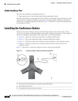
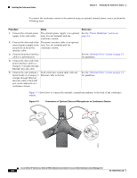
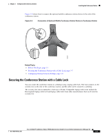
Chapter 3 Setting Up the Conference Station Understanding the Conference Station Components The following warnings apply when you use an external power supply. Warning This product relies on the building's installation for short-circuit (overcurrent) protection. Ensure that a fuse or circuit breaker no larger than 120 VAC, 15 A U.S. (240 VAC, 10 A international) is used on the phase conductors (all current-carrying conductors). Warning The device is designed to work with TN power systems. Warning The plug-socket combination must be accessible at all times because it serves as the main disconnecting device. Understanding the Conference Station Components The conference station includes these components: • Network Ports • Audio Auxiliary Port Network Ports The underside of the conference station includes these connector ports: • Ethernet network port (RJ-45)-Labeled "LAN" • Two external microphone ports (mini-VGA)-Labeled with stenciled microphone icons Each type of port supports 10/100 Mbps half- or full-duplex connections to external devices. You can use either Category 3 or 5 cabling for 10-Mbps connections, but you must use Category 5 for 100 Mbps connections. Use the Ethernet network port to connect the conference station to the network. You must use a straight-through cable on this port. The conference station can also obtain inline power from a switch over this connection (Power over Ethernet). Figure 3-1 shows how to connect the conference station to the network using Power over Ethernet (PoE). If you use an external power source, rather than PoE, to connect the conference station to the network, see Figure 3-2. For more information on powering the conference station, see the "Providing Power to the Conference Station" section on page 2-2. Use the external microphone ports to connect optional external microphones to the conference station. Figure 3-3 shows how to connect the optional microphones to the conference station. Cisco Unified IP Conference Station 7937G Administration Guide for Cisco Unified Communications Manager 6.0 OL-11560-01 Rev. B0 3-3
-
 1
1 -
2
-
3
-
4
-
5
-
6
-
7
-
8
-
9
-
10
-
11
-
12
-
13
-
14
-
15
-
16
-
17
-
18
-
19
-
20
-
21
-
22
-
23
-
24
-
25
-
26
-
27
-
28
-
29
-
30
-
31
-
32
-
33
-
 34
34 -
 35
35 -
 36
36 -
 37
37 -
 38
38 -
 39
39 -
 40
40 -
 41
41 -
 42
42 -
 43
43 -
 44
44 -
45
-
46
-
47
-
48
-
49
-
50
-
51
-
52
-
53
-
54
-
55
-
56
-
57
-
58
-
59
-
60
-
61
-
62
-
63
-
64
-
65
-
66
-
67
-
68
-
69
-
70
-
71
-
72
-
73
-
74
-
75
-
76
-
77
-
78
-
79
-
80
-
81
-
82
-
83
-
84
-
85
-
86
-
87
-
88
-
89
-
90
-
91
-
92
-
93
-
94
-
95
-
96
-
97
-
98
-
99
-
100
-
101
-
102
-
103
-
104
-
105
-
106
-
107
-
108
-
109
-
110
-
111
-
112
-
113
-
114
-
115
-
116
-
117
-
118
-
119
-
120
-
121
-
122
 |
 |
