Cisco CP-7937G Administration Guide - Page 42
Connection of Optional External Microphones to Conference Station, for guidelines.
 |
View all Cisco CP-7937G manuals
Add to My Manuals
Save this manual to your list of manuals |
Page 42 highlights
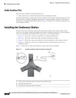
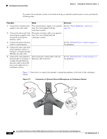
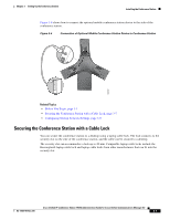
Installing the Conference Station Chapter 3 Setting Up the Conference Station To connect the conference station to the network using an optional external power source, perform the following steps: Procedure 1. Connect the external power supply to the wall outlet. 2. Connect the other end of the external power supply to the receptacle on the power interface cable. 3. Connect the power interface cable to a network port. 4. Connect the other end of the power interface cable to a Category 5 straight-through Ethernet network cable. 5. Connect the end (without a ferrite bead) of a Category 5 straight-through Ethernet network cable to the LAN port on the underside of a conference station. Notes The external power supply is an optional item. It is not included with the conference station. The power interface cable is an optional item. It is not included with the conference station. Each conference station ships with one Ethernet cable in the box. Reference See the "Power Guidelines" section on page 2-3. See the "Network Ports" section on page 3-3 for guidelines. See the "Network Ports" section on page 3-3 for guidelines. Figure 3-3 shows how to connect the optional, external microphones to the back of the conference station. Figure 3-3 Connection of Optional External Microphones to Conference Station 185260 Cisco Unified IP Conference Station 7937G Administration Guide for Cisco Unified Communications Manager 6.0 3-6 OL-11560-01 Rev. B0
-
 1
1 -
2
-
3
-
4
-
5
-
6
-
7
-
8
-
9
-
10
-
11
-
12
-
13
-
14
-
15
-
16
-
17
-
18
-
19
-
20
-
21
-
22
-
23
-
24
-
25
-
26
-
27
-
28
-
29
-
30
-
31
-
32
-
33
-
34
-
35
-
36
-
 37
37 -
 38
38 -
 39
39 -
 40
40 -
 41
41 -
 42
42 -
 43
43 -
 44
44 -
 45
45 -
 46
46 -
 47
47 -
48
-
49
-
50
-
51
-
52
-
53
-
54
-
55
-
56
-
57
-
58
-
59
-
60
-
61
-
62
-
63
-
64
-
65
-
66
-
67
-
68
-
69
-
70
-
71
-
72
-
73
-
74
-
75
-
76
-
77
-
78
-
79
-
80
-
81
-
82
-
83
-
84
-
85
-
86
-
87
-
88
-
89
-
90
-
91
-
92
-
93
-
94
-
95
-
96
-
97
-
98
-
99
-
100
-
101
-
102
-
103
-
104
-
105
-
106
-
107
-
108
-
109
-
110
-
111
-
112
-
113
-
114
-
115
-
116
-
117
-
118
-
119
-
120
-
121
-
122
 |
 |
