Craftsman 22124 Owners Manual - Page 17
Assembly
 |
View all Craftsman 22124 manuals
Add to My Manuals
Save this manual to your list of manuals |
Page 17 highlights
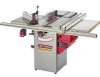
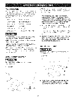
POLY=V BELT ASSEMBLY MAKE CERTAIN the table saw is disconnected from the power source. Figure 6=1 B ; c 1, CAUTION: The extension wings are heavy; two people are required to assemble both extension wings to the table saw. 2, Assemble one of the extension wings (A) to the left side of the table saw. Align the four holes (B) in the extension wing with the four holes in the left side of the saw table. Use four M8 x 30mm hex head screws, M8 lock washers and M8 flat washers. Do not completely tighten hardware at this time. See figure 7-1. Figure 7=2 D E 1, Make sure all packaging material has been removed from inside the cabinet. 2. Open the motor cover and place the motor Poly-V belt (A) over the blade pulley (B). See figure 6-1. 3. Carefully lift the motor (C) and place the belt under the motor pulley (not shown). Make sure all the v-notches in the belt are mated with the v-notches of the blade and motor pulley. See figure 6-1. 4, Carefully let the motor down and close motor cover. EXTENSION WING ASSEMBLY MAKE CERTAIN the table saw is disconnected from the power source. The right extension wing must be completely assembled and motor cover closed and fastened before table saw is to be connected to the power source. Figure 7=1 A 3, Lay a straight edge (C) across the saw table (D) and extension wing (E). Make sure that the front face of the extension wing (F) is flat to the front face of the saw table (G). Adjust the extension wing so that its top surface is exactly flat to the saw table and securely tighten hardware. See figure 7-2. 4, Repeat steps 2 and 3 above to assemble the other extension wing to the right side of the table saw. HANDWHEEL ASSEMBLY MAKE CERTAIN the table saw is disconnected from the power source. Figure 8=1 D C 17
-
 1
1 -
2
-
3
-
4
-
5
-
6
-
7
-
8
-
9
-
10
-
11
-
 12
12 -
 13
13 -
 14
14 -
 15
15 -
 16
16 -
 17
17 -
 18
18 -
 19
19 -
 20
20 -
 21
21 -
 22
22 -
23
-
24
-
25
-
26
-
27
-
28
-
29
-
30
-
31
-
32
-
33
-
34
-
35
-
36
-
37
-
38
-
39
-
40
-
41
-
42
-
43
-
44
-
45
-
46
-
47
-
48
-
49
-
50
-
51
-
52
-
53
-
54
-
55
-
56
-
57
-
58
-
59
-
60
-
61
-
62
-
63
-
64
-
65
-
66
-
67
-
68
-
69
-
70
-
71
-
72
-
73
-
74
-
75
-
76
-
77
-
78
-
79
-
80
-
81
-
82
-
83
-
84
-
85
-
86
-
87
-
88
 |
 |
