Craftsman 22124 Owners Manual - Page 23
Connecting, Switch, To Motor
 |
View all Craftsman 22124 manuals
Add to My Manuals
Save this manual to your list of manuals |
Page 23 highlights
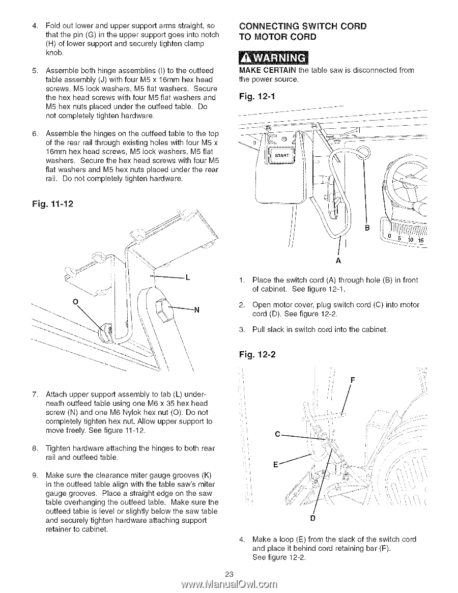
4, Fold out lower and upper support arms straight, so that the pin (G) in the upper support goes into notch (H) of lower support and securely tighten clamp knob. 5, Assemble both hinge assemblies (I) to the outfeed table assembly (J) with four M5 x 16mm hex head screws, M5 lock washers, M5 flat washers. Secure the hex head screws with four M5 flat washers and M5 hex nuts placed under the outfeed table. Do not completely tighten hardware. 6, Assemble the hinges on the outfeed table to the top of the rear rail through existing holes with four M5 x 16mm hex head screws, M5 lock washers, M5 flat washers. Secure the hex head screws with four M5 flat washers and M5 hex nuts placed under the rear rail. Do not completely tighten hardware. CONNECTING SWITCH CORD TO MOTOR CORD MAKE CERTAIN the table saw is disconnected from the power source. Fig. 12-1 Fig. 11-12 A 1, Place the switch cord (A) through hole (B) in front of cabinet. See figure 12-1. 2, Open motor cover, plug switch cord (C) into motor cord (D). See figure 12-2. 3. Pull slack in switch cord into the cabinet. Fig. 12-2 7, Attach upper support assembly to tab (L) under- neath outfeed table using one M6 x 35 hex head screw (N) and one M6 Nylok hex nut (O). Do not completely tighten hex nut. Allow upper support to / move freely. See figure 11-12. 8, Tighten hardware attaching the hinges to both rear rail and outfeed table. 9, Make sure the clearance miter gauge grooves (K) in the outfeed table align with the table saw's miter gauge grooves. Place a straight edge on the saw table overhanging the outfeed table. Make sure the outfeed table is level or slightly below the saw table and securely tighten hardware attaching support retainer to cabinet. 4. Make a loop (E) from the slack of the switch cord and place it behind cord retaining bar (F). See figure 12-2. 23
-
 1
1 -
2
-
3
-
4
-
5
-
6
-
7
-
8
-
9
-
10
-
11
-
12
-
13
-
14
-
15
-
16
-
17
-
 18
18 -
 19
19 -
 20
20 -
 21
21 -
 22
22 -
 23
23 -
 24
24 -
 25
25 -
 26
26 -
 27
27 -
 28
28 -
29
-
30
-
31
-
32
-
33
-
34
-
35
-
36
-
37
-
38
-
39
-
40
-
41
-
42
-
43
-
44
-
45
-
46
-
47
-
48
-
49
-
50
-
51
-
52
-
53
-
54
-
55
-
56
-
57
-
58
-
59
-
60
-
61
-
62
-
63
-
64
-
65
-
66
-
67
-
68
-
69
-
70
-
71
-
72
-
73
-
74
-
75
-
76
-
77
-
78
-
79
-
80
-
81
-
82
-
83
-
84
-
85
-
86
-
87
-
88
 |
 |