Craftsman 22124 Owners Manual - Page 19
Craftsman 22124 - Professional 10 in. Table Saw Manual
 |
View all Craftsman 22124 manuals
Add to My Manuals
Save this manual to your list of manuals |
Page 19 highlights
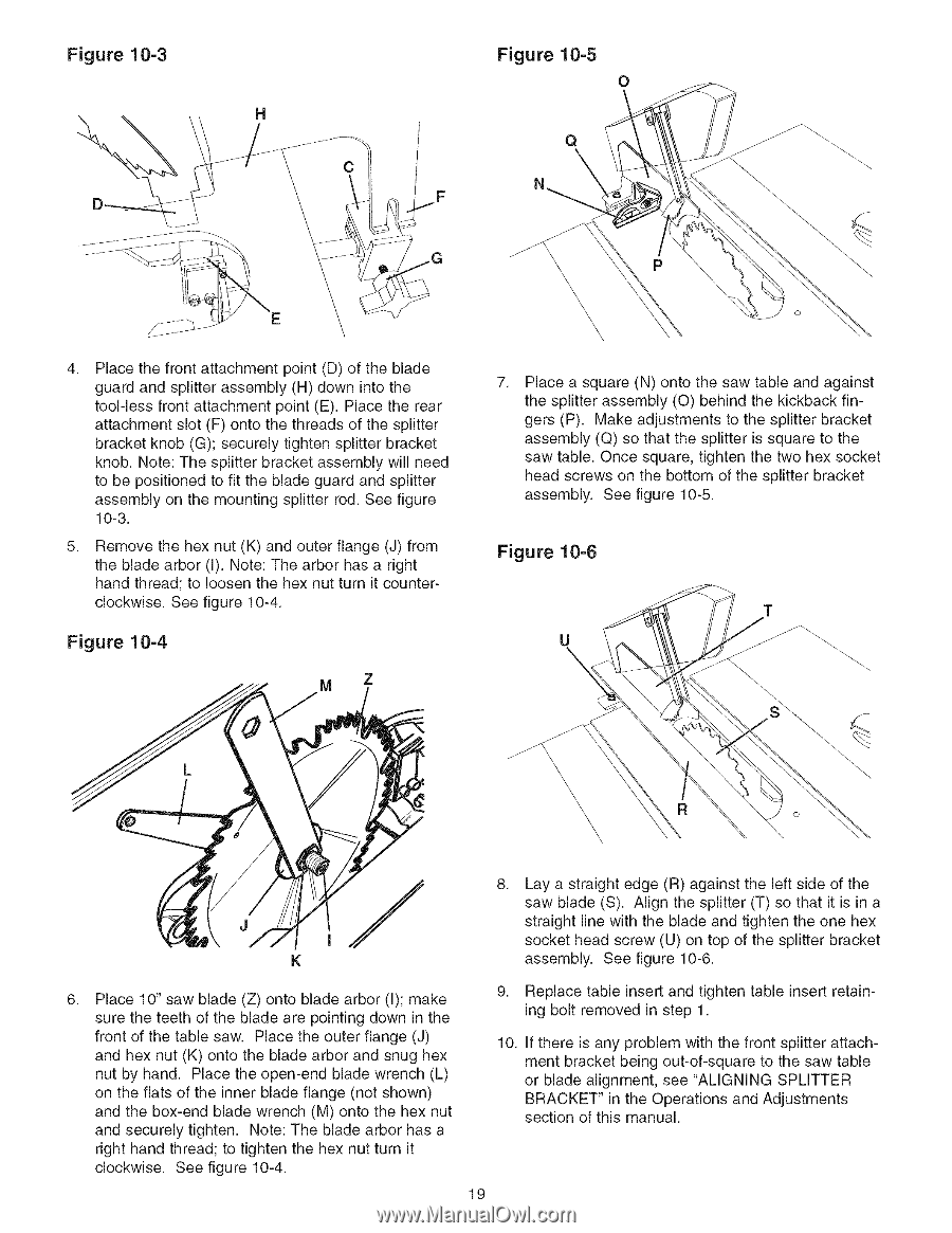
Figure 10=3 \ C 4. Place the front attachment point (D) of the blade guard and splitter assembly (H) down into the tool-less front attachment point (E). Place the rear attachment slot (F) onto the threads of the splitter bracket knob (G); securely tighten splitter bracket knob. Note: The splitter bracket assembly will need to be positioned to fit the blade guard and splitter assembly on the mounting splitter rod. See figure 10-3. 5. Remove the hex nut (K) and outer flange (J) from the blade arbor (I). Note: The arbor has a right hand thread; to loosen the hex nut turn it counterclockwise. See figure 10-4. Figure 10=4 M Figure 10=5 o \ \ \ \ \ \, \ \ \. \\ \\\\\ \\\ \ 7. Place a square (N) onto the saw table and against the splitter assembly (0) behind the kickback fingers (P). Make adjustments to the splitter bracket assembly (Q) so that the splitter is square to the saw table. Once square, tighten the two hex socket head screws on the bottom of the splitter bracket assembly. See figure 10-5. Figure 10=6 T \\\ \ \ \. 8. Lay a straight edge (R) against the left side of the saw blade (S). Align the splitter (T) so that it is in a straight line with the blade and tighten the one hex socket head screw (U) on top of the splitter bracket assembly. See figure 10-6. 6. Place 10" saw blade (Z) onto blade arbor (I); make sure the teeth of the blade are pointing down in the front of the table saw. Place the outer flange (J) and hex nut (K) onto the blade arbor and snug hex nut by hand. Place the open-end blade wrench (L) on the flats of the inner blade flange (not shown) and the box-end blade wrench (M) onto the hex nut and securely tighten. Note: The blade arbor has a right hand thread; to tighten the hex nut turn it clockwise. See figure 10-4. 9. Replace table insert and tighten table insert retaining bolt removed in step 1. 10. If there is any problem with the front splitter attachment bracket being out-of-square to the saw table or blade alignment, see "AMGNING SPMTTER BRACKET" in the Operations and Adjustments section of this manual. 19
-
 1
1 -
2
-
3
-
4
-
5
-
6
-
7
-
8
-
9
-
10
-
11
-
12
-
13
-
 14
14 -
 15
15 -
 16
16 -
 17
17 -
 18
18 -
 19
19 -
 20
20 -
 21
21 -
 22
22 -
 23
23 -
 24
24 -
25
-
26
-
27
-
28
-
29
-
30
-
31
-
32
-
33
-
34
-
35
-
36
-
37
-
38
-
39
-
40
-
41
-
42
-
43
-
44
-
45
-
46
-
47
-
48
-
49
-
50
-
51
-
52
-
53
-
54
-
55
-
56
-
57
-
58
-
59
-
60
-
61
-
62
-
63
-
64
-
65
-
66
-
67
-
68
-
69
-
70
-
71
-
72
-
73
-
74
-
75
-
76
-
77
-
78
-
79
-
80
-
81
-
82
-
83
-
84
-
85
-
86
-
87
-
88
 |
 |