Craftsman 24838 Operation Manual - Page 11
SEE FRONT, suspension, included, TRACTOR
 |
View all Craftsman 24838 manuals
Add to My Manuals
Save this manual to your list of manuals |
Page 11 highlights
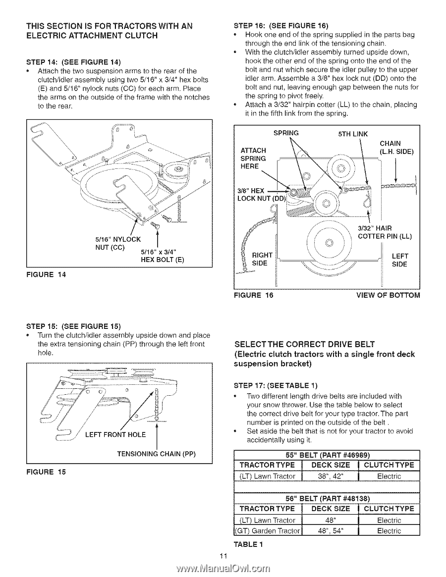
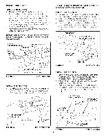
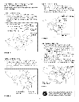
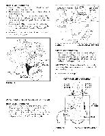
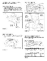
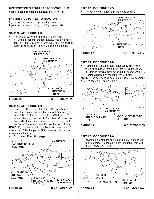
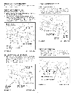
THIS SECTION IS FOR TRACTORS WITH AN ELECTRIC ATTACHMENT CLUTCH STEP 14: (SEE FIGURE 14) Attach the two suspension arms to the rear of the clutch/idler assembly using two 5/16" x 3/4" hex bolts (E) and 5/16" nylock nuts (CO) for each arm Place the arms on the outside of the frame with the notches to the rear STEP 16: (SEE FIGURE 16) • Hook one end of the spring supplied in the parts bag through the end link of the tensioning chain • With the clutch/idler assembly turned upside down, hook the other end of the spring onto the end of the bolt and nut which secure the idler pulley to the upper idler arm. Assemble a 3/8" hex lock nut (DD) onto the bolt and nut, leaving enough gap between the nuts for the spring to pivot freely. • Attach a 3/32" hairpin cotter (LL) to the chain, placing it in the fifth link from the spring. SPRING ATTACH SPRING HERE 5TH LINK CHAIN (L.N. SIDE) 1 LOCK NUT FIGURE 14 5/16" NYLOCK l NUT (CC) 5/16" x 3/4" HEX BOLT (E) FIGURE 16 3/32" HAIR COTTER PIN (LL) ' \\ //"' ' ' LEFT SIDE ViEW OF BOTTOM STEP 16: (SEE FIGURE 15) Turn the clutch/idler assembly upside down and place the extra tensioning chain (PP) through the left front hole. SELECTTHE CORRECT (Electric clutch tractors suspension bracket) DRIVE BELT with a single front deck r ,' LEFT FRONT HOLE FIGURE 16 TENSIONING CHAIN (PP) STEP 17: (SEETABLE 1) Two different length drive belts are included with your snow thrower. Use the table below to select the correct drive belt for your type tractor The part number is printed on the outside of the belt Set aside the belt that is not for your tractor to avoid accidentally using it 55" BELT (PART #46989) T(LRTA) CLTawOnR TTraYcPtoEr t DE3C8K", 4S2iZ" E ][ CLUTECleHctriTcYPE 56" BELT (PART #48138) T(LRTA) CLTaOwRn TTraYcPtoEr (GT) Garden Tractor TABLE 1 11 DECK48"SIZE l CLUTECleHctTriYcPE 48", 54" Electric
-
 1
1 -
2
-
3
-
4
-
5
-
 6
6 -
 7
7 -
 8
8 -
 9
9 -
 10
10 -
 11
11 -
 12
12 -
 13
13 -
 14
14 -
 15
15 -
 16
16 -
17
-
18
-
19
-
20
-
21
-
22
-
23
-
24
-
25
-
26
-
27
-
28
-
29
-
30
-
31
-
32
-
33
-
34
-
35
-
36
-
37
-
38
-
39
-
40
 |
 |