Craftsman 24838 Operation Manual - Page 8
Mounting, Plate, Right, Step 5, Inside
 |
View all Craftsman 24838 manuals
Add to My Manuals
Save this manual to your list of manuals |
Page 8 highlights
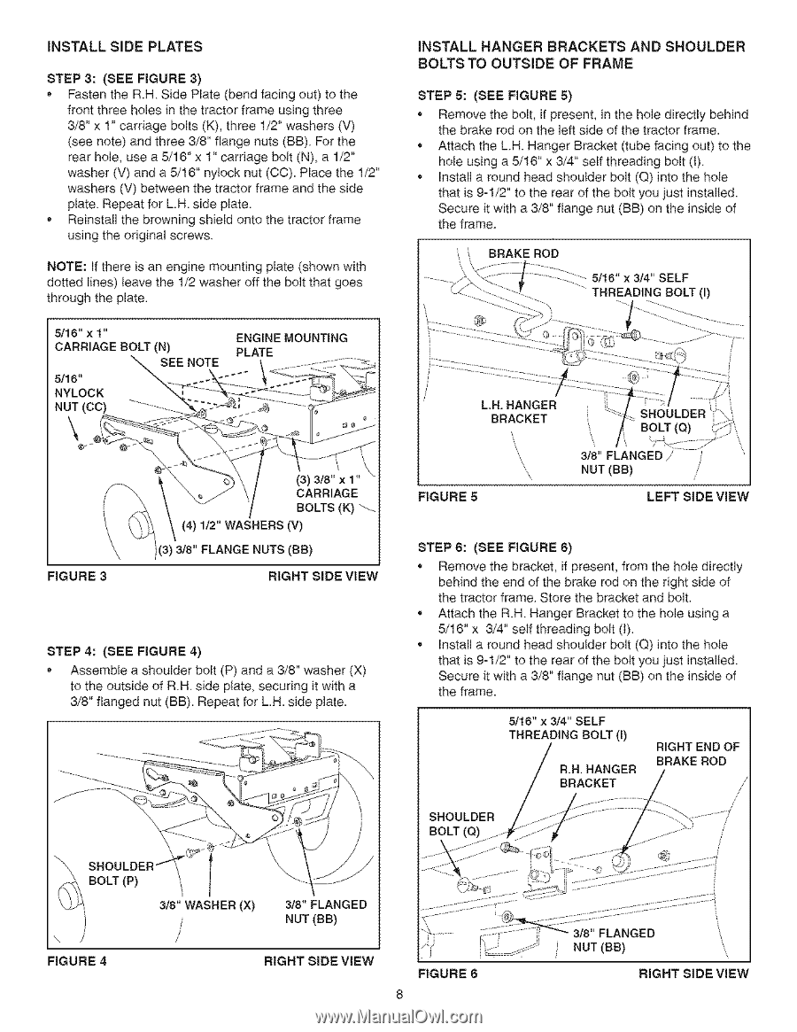
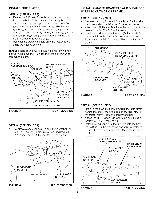
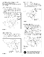
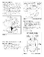
INSTALL SIDE PLATES STEP 3: (BEE FIGURE 3) * Fasten the R.H Side Plate (bend facing out) to the front three holes in the tractor frame using three 3/8" x 1" carriage bolts (K), three 1/2" washers (V) (see note) and three 3/8" flange nuts (BB) For the rear hole, use a 5/16" x 1" cardage bolt (N), a 1/2" washer (V) and a 5/16" nyiock nut (CC). Place the 1/2" washers (V) between the tractor frame and the side plate Repeat for L.H. side plate• * Reinstall the browning shield onto the tractor frame using the odginal screws NOTE: If there is an engine mounting plate (shown with dotted lines) leave the 1/2 washer off the bolt that goes through the plate. 7 5/16" x 1" CARRIAGE BOLT (N) ENGINE MOUNTING PLATE || SEE NOTE 5/16" NYLOCK NUT (CC) ..... - i \ FIGURE 3 (3) CARRIAGE BOLTS (K) _-(4) 1/2" WASHERS (V) i )(3) 3/8" FLANGE NUTS (BB) RIGHT BIDE VIEW STEP 4: (SEE FIGURE 4) Assemble a shoulder bolt (P) and a 3/8" washer (X) 1o the outside of RH side plate, securing it with a 3/8" flanged nut (BB). Repeat fo_ L.H. side plate. INSTALL HANGER BRACKETS AND SHOULDER BOLTS TO OUTSIDE OF FRAME STEP 5: (BEE FIGURE 8) • Remove the bolt, if present, in the hole directly behind the brake rod on the left side of the tractor frame• • Attach the L.H. Hanger Bracket (tube facing out) to the hole using a 5/16" x 3/4" self threading bolt (1) • Install a round head shoulder bolt (Q) into the hole that is 9-1/2" to the rear of the bolt you just installed• Secure it with a 3/8" flange nut (BB) on the inside of the frame. BRAKEROD THREADING BO_(I) LN. HANGER i BRACKET FIGURE8 _8"FLANGEDi NUT (BB) LEFT SIDE ViEW STEP 6: (BEE FIGURE 6) Remove the bracket, if present, from the hole directly behind the end of the brake rod on the right side of the tractor frame Store the bracket and bolt. • Attach the R.H Hanger Bracket to the hole using a 5/16" x 3/4" serf threading bolt (I). • Install a round head shoulder bolt (Q) into the hole that is 9-1/2" to the rear of the bolt you just installed. Secure it with a 3/8" flange nut (BB) on the inside of the frame. 5/16" x 3/4" SELF THREADING BOLT (I) R.H. HANGER BRACKET RIGHT END OF BRAKE ROD SHOULDER BOLT (Q) J FIGURE 4 RIGHT BiDE VIEW FIGURE 6 1 :1:1_ i 3/8 FLANGED NUT (BB) RIGHT SIDE ViEW
-
 1
1 -
2
-
 3
3 -
 4
4 -
 5
5 -
 6
6 -
 7
7 -
 8
8 -
 9
9 -
 10
10 -
 11
11 -
 12
12 -
 13
13 -
14
-
15
-
16
-
17
-
18
-
19
-
20
-
21
-
22
-
23
-
24
-
25
-
26
-
27
-
28
-
29
-
30
-
31
-
32
-
33
-
34
-
35
-
36
-
37
-
38
-
39
-
40
 |
 |