Craftsman 24838 Operation Manual - Page 17
inside, idler, STEP 38, lever
 |
View all Craftsman 24838 manuals
Add to My Manuals
Save this manual to your list of manuals |
Page 17 highlights
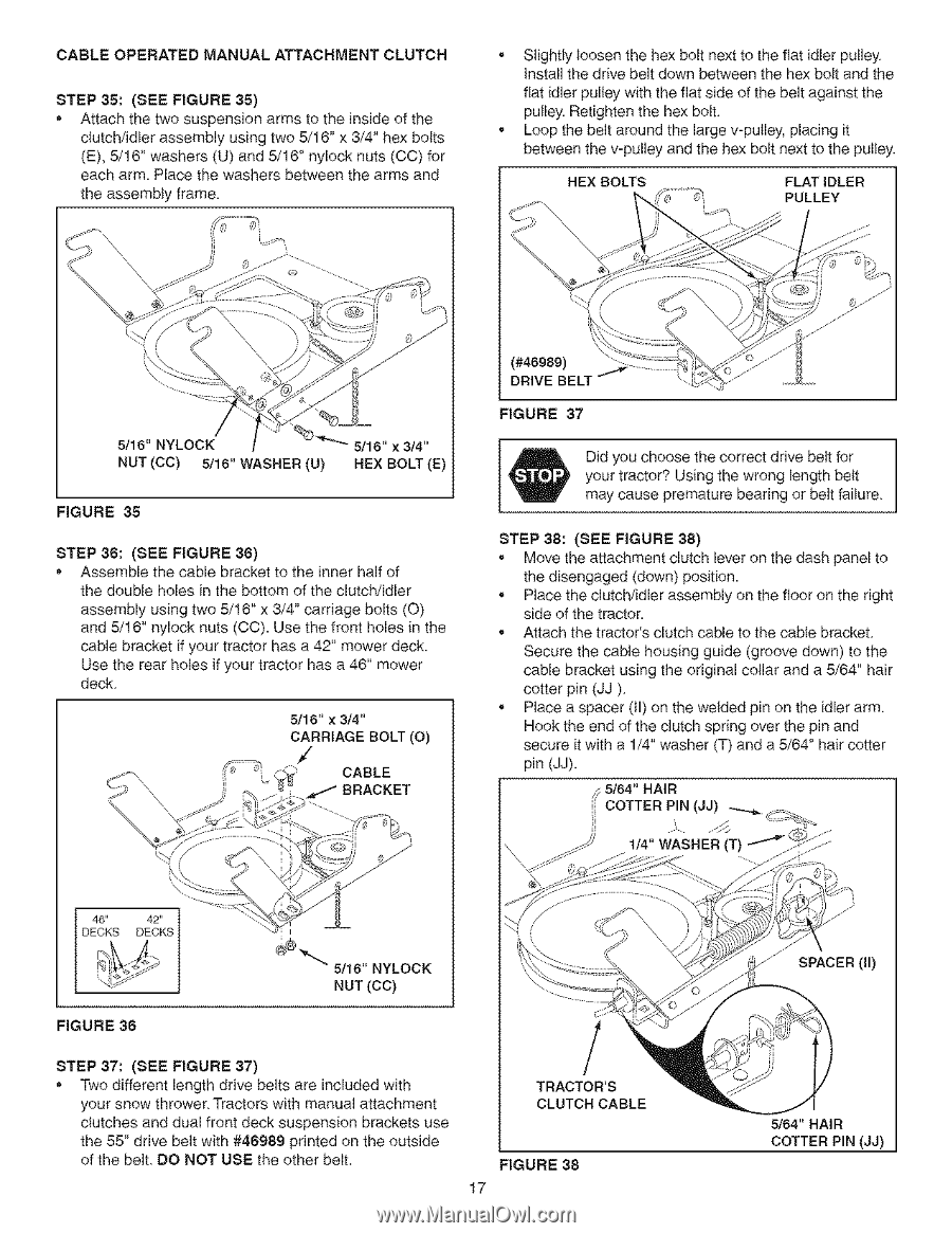
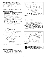
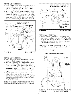
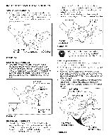
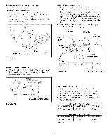
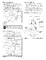
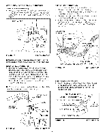
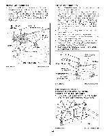
CABLE OPERATED MANUAL ATTACHMENT CLUTCH STEP 35: (SEE FIGURE 35) • Attach the two suspension arms to the inside of the clutch/idler assembly using two 5/16" x 3/4" hex bolts (E), 5/16" washers (U) and 5/16" nylock nuts (CO) for each arm. Place the washers between the arms and the assembly frame. , Slightly loosen the hex bolt next to the flat idler pulley Install the drive belt down between the hex bolt and the flat idler pulley with the flat side o1 the belt against the puEley.Retighten the hex bolt , Loop the belt around the large v-pulley, placing it between the v-pulley and the hex bolt next to the pulley. HEX BOLTS FLATIDLER PULLEY 5/16" NYLOCK NUT (CC) 5/16" WASHER (U) 5/16" x 3/4" HEX BOLT (E) FIGURE 35 STEP 36: (SEE FIGURE 36) • Assemble the cable bracket to the inner half of the double holes in the bottom of the clutch/idler assembly using two 5/16" x 3/4" carriage bolts (O) and 5/16" nylock nuts (CC). Use the front holes in the cable bracket if your tractor has a 42" mower deck. Use the rear holes if your tractor has a 46" mower deck 5/16" x 3/4" CARRIAGE BOLT (O) ' __ CABLE (#46989) DRIVE BELT FIGURE 37 Did you choose the correct drive belt for your tractor? Using the wrong length belt may cause premature bearing or belt failure STEP 38: (SEE FIGURE 38) ° Move the attachment clutch lever on the dash panel to the disengaged (down) position. • Place the clutch/idler assembly on the floor on the right side of the tractor. , Attach the tractor's clutch cable to the cable bracket Secure the cable housing guide (groove down) to the cable bracket using the original collar and a 5/64" hair cotter pin (JJ) • Place a spacer (ll) on the welded pin on the idler arm. Hook the end of the clutch spring over the pin and secure it with a 1/4" washer (T) and a 5/64" hair cotter pin (JJ). ,_5/64" HAIR [( COTTER PIN (JJ) i 1/4" WASHER (T) 5/16" NYLOCK NUT (CC) FIGURE 36 STEP 37: (SEE FIGURE 37) • Two different length drive belts are included with your snow thrower Tractors with manual attachment clutcl_es and dual front deck suspension brackets use the 55" drive belt with #46989 pdnted on the outside of the belt DO NOT USE the other belt. / TRACTOR'S CLUTCH CABLE FIGURE 38 17 SPACER (ll) 5/64" HAIR COTTER PIN (JJ)
-
 1
1 -
2
-
3
-
4
-
5
-
6
-
7
-
8
-
9
-
10
-
11
-
 12
12 -
 13
13 -
 14
14 -
 15
15 -
 16
16 -
 17
17 -
 18
18 -
 19
19 -
 20
20 -
 21
21 -
 22
22 -
23
-
24
-
25
-
26
-
27
-
28
-
29
-
30
-
31
-
32
-
33
-
34
-
35
-
36
-
37
-
38
-
39
-
40
 |
 |