Craftsman 24838 Operation Manual - Page 7
Right hand R.H - snow thrower manual
 |
View all Craftsman 24838 manuals
Add to My Manuals
Save this manual to your list of manuals |
Page 7 highlights
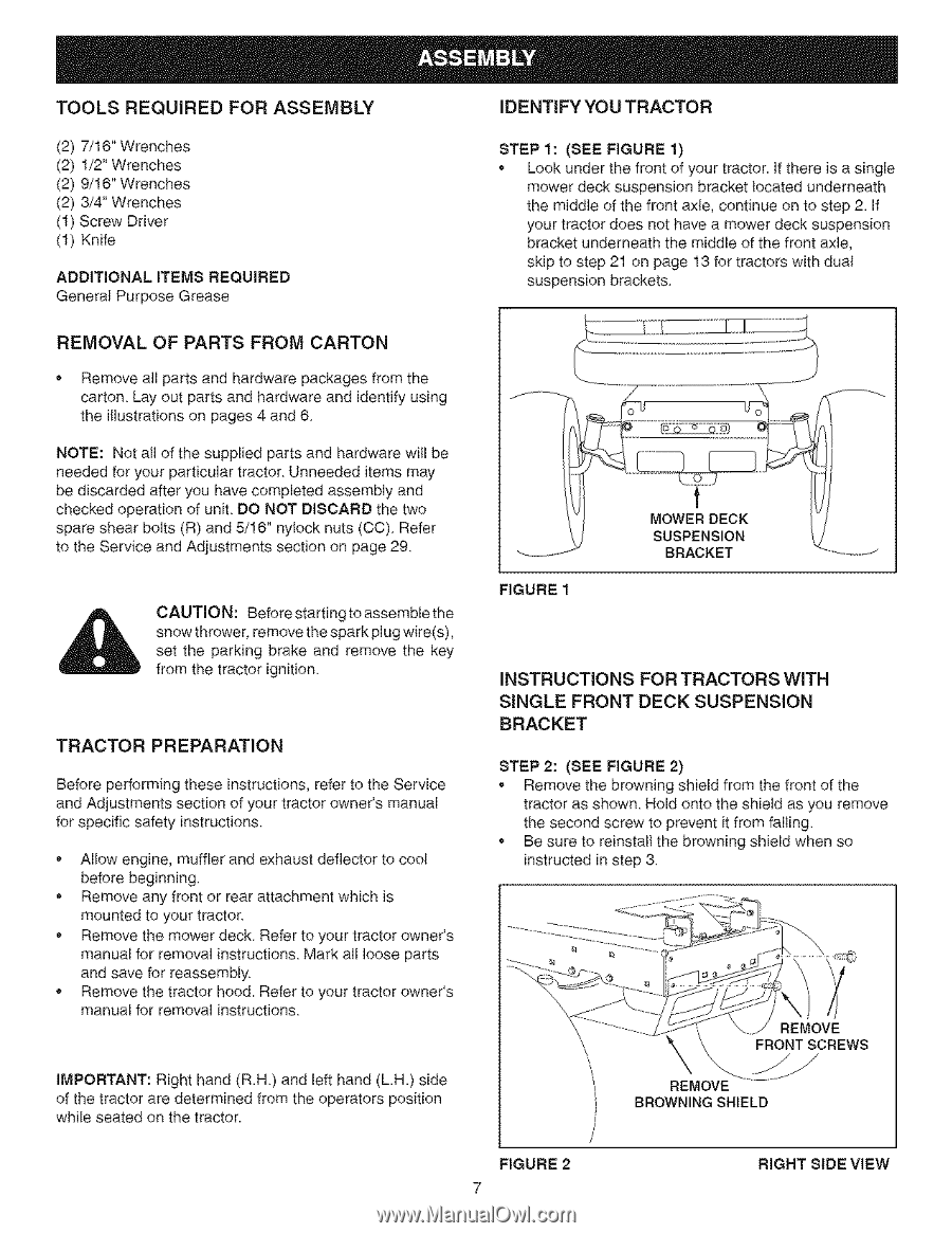
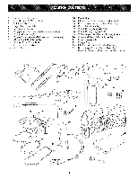
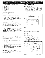
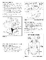
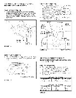
TOOLS REQUIRED FOR ASSEMBLY (2) 7/16" Wrenches (2) 1/2" Wrenches (2) 9/16" Wrenches (2) 3/4" Wrenches (1) Screw Driver (1) Knife ADDITIONAL ITEMS REQUIRED General Purpose Grease IDENTIFYYOUTRACTOR STEP 1: (SEE FIGURE 1) Look under the front of your tractor. If there is a single mower deck suspension bracket located underneath the middle of the front axle, continue on to step 2. If your tractor does not have a mower deck suspension bracket underneath the middle of the front axle, skip to step 21 on page 13 for tractors with dual suspension brackets REMOVAL OF PARTS FROM CARTON * Remove all parts and hardware packages from the carton Lay out parts and hardware and identify using the illustrations on pages 4 and 6 NOTE: Not all of the supplied parts and hardware will be needed for your particular tractor Unneeded items may be discarded after you have completed assembly and checked operation of unit DO NOT DISCARD the two spare shear bolts (R) and 5/16" nylock nuts (CO) Refer to the Service and Adjustments section on page 29 CAUTION: Before starting to assemble the snow thrower, remove the spark plug wire(s), set the parking brake and remove the key from the tractor ignition TRACTOR PREPARATION Before performing these instructions, refer to the Service and Adjustments section of your tractor owner's manual for specific safety instructions. • Allow engine, muffler and exhaust deflector to cool before beginning • Remove any front or rear attachment which is mounted to your tractor • Remove the mower deck Refer to your tractor owner's manual for removal instructions Mark all loose parts and save for reassembly • Remove the tractor hood. Refer to your tractor owneCs manual for removal instructions IMPORTANT: Right hand (R.H) and left hand (L.H.) side of the tractor are determined from the operators position while seated on the t{actor. FIGURE 1 MOWERDECK SUSPENSION BRACKET INSTRUCTIONS SINGLE FRONT BRACKET FOR TRACTORS WiTH DECK SUSPENSION STEP 2: (SEE FIGURE 2) • Remove the browning shield from the front of the tractor as shown Hold onto the shield as you remove the second screw to prevent it from falling Be sure to reinstall the browning shield when so instructed in step 3 REMOVE FRONTSCREWS REMOVE BROWNING SHIELD FIGURE 2 7 RIGHT 61DE VIEW
-
 1
1 -
 2
2 -
 3
3 -
 4
4 -
 5
5 -
 6
6 -
 7
7 -
 8
8 -
 9
9 -
 10
10 -
 11
11 -
 12
12 -
13
-
14
-
15
-
16
-
17
-
18
-
19
-
20
-
21
-
22
-
23
-
24
-
25
-
26
-
27
-
28
-
29
-
30
-
31
-
32
-
33
-
34
-
35
-
36
-
37
-
38
-
39
-
40
 |
 |