Craftsman 24838 Operation Manual - Page 26
Checklist - sears snow
 |
View all Craftsman 24838 manuals
Add to My Manuals
Save this manual to your list of manuals |
Page 26 highlights
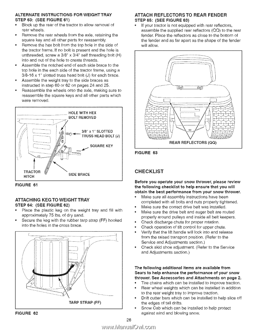
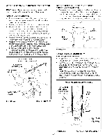
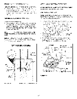
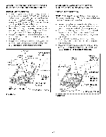
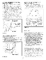
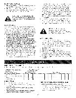
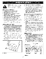
ALTERNATE INSTRUCTIONS FOR WEIGRTTRAY STEP 83: (SEE FIGURE 61) Block up the rea_ of the tractor to allow removal of rear wheels. Remove the rear wheels from the axle, retaining the square key and all other parts for reassembly Remove the hex bolt from the top hole in the side of the tractor frame. If no bolt is present and the hole is unthreaded, screw a 3/8" x 3/4" self threading bolt (H) into and out of the hole to create threads Assemble the notched end of each side brace to the top hole in the each side of the tractor frame, using a 3/8-18 x 1" slotted truss head bolt (J) for each brace * Assemble the weight tray to the side braces as instructed in step 80 or 62 on pages 24 and 25. * Reassemble the wheels onto the axle, making sure to reassemble the square keys and all other parts which were removed DOLE WITH HEX BO_HEMOVED t TRACTOR HITCH FIGURE 81 3/8" x 1" SLOTTED mUSS HEAD DOLT (J) SQUARE KEY SIDE BRACE ATTACHING KEG TO WEIGHTTRAY STEP 64: (SEE FIGURE 62) * Place the ptastic keg on the weight tray and fill with approximately 75 Ibs. of dry sand. * Secure the keg with the rubber tarp strap (FF) hooked into the holes in the cross brace. / ! ATTACH REFLECTORS TO REAR FENDER STEP 68: (SEE FIGURE 63) • If your tractor is not equipped with rear reflectors, assemble the supplied rear reflectors (QQ) to the rear fender Place the reflectors as close to the bottom of the fender and as far apart as the shape of the fender will allow. \ FIGURE 63 REAR REFLECTORS (QQ) CHECKLIST Before you operate your snow thrower, please review the following checklist to help ensure that you will obtain the best performance from your snow thrower. • Make sure air assembly instructions have been completed with aH bolts and nuts properly tightened. • Make sure the correct dbve belt was installed. • Make sure the drive belt and auger belt are routed properly around pulleys and inside all belt keepers • Check discharge chute for proper rotation • Check operation of tilt control for upper chute • Verify that the _ift handle will lock into and release from the raised transport position. (Refer to the Service and Adjustments section.) • Check skid shoe adjustment (Refer to the Service and Adjustments section.) FIGURE 62 TARP STRAP (FF) The following additional items are available from Sears to help enhance the performance of your snow thrower. See Accessories and Attachments on page 2. • Tire chains which can be installed to improve traction • Rear wheel weights which can be installed in addition to the rear weight tray to improve traction. • Drift cutter bars which can be installed to help slice off the edges of tall drifts • Snow Cab which can be installed to help protect against wind and blowing snow. 28
-
 1
1 -
2
-
3
-
4
-
5
-
6
-
7
-
8
-
9
-
10
-
11
-
12
-
13
-
14
-
15
-
16
-
17
-
18
-
19
-
20
-
 21
21 -
 22
22 -
 23
23 -
 24
24 -
 25
25 -
 26
26 -
 27
27 -
 28
28 -
 29
29 -
 30
30 -
 31
31 -
32
-
33
-
34
-
35
-
36
-
37
-
38
-
39
-
40
 |
 |