Craftsman 24838 Operation Manual - Page 13
Instructions, Fortractorswith, Front, Suspension, Brackets
 |
View all Craftsman 24838 manuals
Add to My Manuals
Save this manual to your list of manuals |
Page 13 highlights
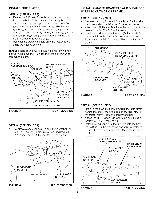
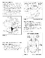
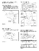
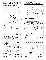
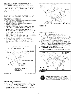
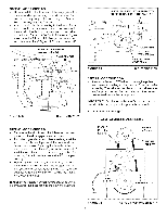
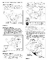
iNSTRUCTiONS FORTRACTORSWITH DUAL FRONT DECK SUSPENSION BRACKETS FASTEN SIDE PLATES TO TRACTOR If your tractor resembles figure 20, go to step 21. If your tractor resembles figure 22 go to step 23 STEP 21: (SEE FIGURE 20) Remove bolts from front three holes shown If a bolt is present in the fourth hole, replace it with a 5/16" x 1" cardage bolt (N) without a nut The bracket fastened to inside of frame must remain in place REPLACE HOLT (IF PRESENT) REMOVE BOLTS (IF PRESENT) \ FIGURE 20 /, k FRONT SUSPENSION BRACKET RIGHT SiDE ViEW STEP 22: (SEE FIGURE 21) Fasten the RH Side Plate (bend facing out) to the front three holes shown in the tractor frame using three 3/8" x 1" thread forming bolts (G), three 3/8" lock washers (S) and one 1/2" washer (V) placed on the thffd bolt as a shim between the side plate and the frame.Tighten all bolts Repeat for the L.H side. NOTE: If you installed a bolt in the fourth hole in step 21, assemble a 5/16" flange nut (AA) onto the bolt after the side plate is installed. Go to step 28 oH this page. 5/16" x 1" CARRIAGE BOLT (N) (SEE NOTE) 1/2" WASHER (V) STEP 23: (SEE FIGURE 22) Remove any bolts found in the holes shown. REMOVE BOLTS IF PRESENT \ /,/ FIGURE 22 \ \ _ k\ SUSPENSION ii BRACKET RIGHT SIDE VIEW STEP 24: (SEE FIGURE 23) Fasten the RH Side Plate (bend f_cing out) to the three holes shown in the tractor h_me Use three 3/8" x 1" thread forming bolts (G) and 3/8" lock washers (S). Tighten all bolts and repeat for the L.H. side NOTE: If the bolt inserts heely into the front hole, assemble a 3/8" flanged nut (BB) onto the bolt (3) 3/8" LOCK / _, WASHERS(S) (3)3/8"× 1" i THREAD FORMING BOLTS (G) / 3/8" FLANGED NUT (BB) / (SEE NOTE) FIGURE 23 RIGHT SIDE ViEW STEP 28: (SEE FIGURE 24) Assemble a shouEder bolt (P) and a 3/8" washer (X) to the outside of each side plate, securing them with a 3/8" flanged nut (BB) J \ \ 5/16" FLANGED NUT (AA) (SEE NOTE) \ FIGURE 21 (3) 318" x 1" I THREAD FORMING / BOLTS (G) (3) 3/8" LOCK WASHERS (S) RIGHT SiDE VIEW \ SHOULDER BOLT (P) 3/8" WASHER (X) FIGURE 24 13 / / 3/8" FLANGED NUT(BB) RIGHT SIDE VIEW
-
 1
1 -
2
-
3
-
4
-
5
-
6
-
7
-
 8
8 -
 9
9 -
 10
10 -
 11
11 -
 12
12 -
 13
13 -
 14
14 -
 15
15 -
 16
16 -
 17
17 -
 18
18 -
19
-
20
-
21
-
22
-
23
-
24
-
25
-
26
-
27
-
28
-
29
-
30
-
31
-
32
-
33
-
34
-
35
-
36
-
37
-
38
-
39
-
40
 |
 |
