Craftsman 24838 Operation Manual - Page 14
Foot Rest Brackets, L.H.H.&NGER, iNSTALLING, STEP 27, SEE inside, RIGHT SIDE
 |
View all Craftsman 24838 manuals
Add to My Manuals
Save this manual to your list of manuals |
Page 14 highlights
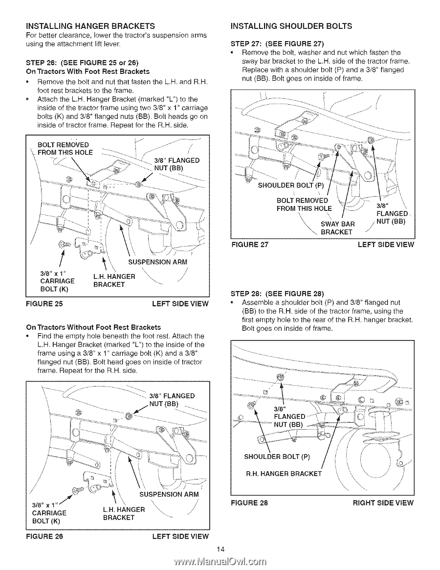
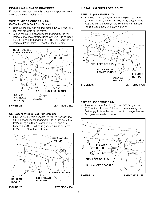
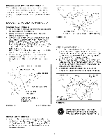
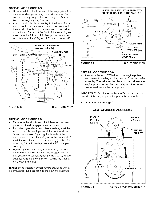
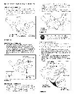
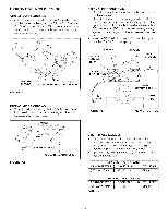
INSTALLING HANGER BRACKETS For better clearance, lower the tractor's suspension arms using the attachment lift lever STEP 26: (SEE FIGURE 25 or28) On Tractors With Foot Rest Brackets • Remove the bolt and nut that fasten the L.H. and R.H. foot rest brackets to the frame • Attach the L.H Hanger Bracket (marked "L") to the inside of the tractor frame using two 3/8" x 1" carriage bolts (K) and 3/8" flanged nuts (BB) Bolt heads go on inside of tractor frame Repeat for the R.H. side. HOLT REMOVED ',, FROM THIS HOLE _// - i..... / 3/8" FLANGED NUT (HB) iNSTALLING SHOULDER BOLTS STEP 27: (SEE FIGURE 27) • Remove the bolt, washer and nut which fasten the sway bar bracket to the LH side of the tractor frame. Replace with a shoulder bolt (P) and a 3/8" flanged nut (BB). Bolt goes on inside of frame. 3/8" x 1" CARRIAGE BOLT (K) FIGURE 25 SUSPENSION ARM LH. HANGER \\. /' BRACKET LEFT SIDE ViEW On Tractors Without Foot Rest Brackets • Find the empty hole beneath the foot rest Attach the L.H Hanger Bracket (marked "L") to the inside of the frame using a 3/8" x 1" carriage bolt (K) and a 3/8" flanged nut (BB) Bolt head goes on inside of tractor frame. Repeat for the RH side 3/8" FLANGED NUT (HH! BOLT REMOVED FROM THIS HOLE k \\ SWAY BAR _. BRACKET 3/8" FLANGED /NHT(BB) / FIGURE 27 LEFT SIDE VIEW STEP 28: (SEE FIGURE 28) • Assemble a shoulder bolt (P) and 3/8" flanged nut (BB) to the RH side of the tractor frame, using the first empty hole to the rear of the R.H. hanger bracket. Bolt goes on inside of frame. / / / 3/8" x 1" f CARRIAGE BOLT (K) FIGURE 28 SHOULDER BOLT (P) R.B. HANGER BRACKET SUSPENSION ARM L.H.H.&NGER "\, / BRACKET FIGURE 28 LEFT SIDE VIEW 14 RIGHT SIDE VIEW
-
 1
1 -
2
-
3
-
4
-
5
-
6
-
7
-
8
-
 9
9 -
 10
10 -
 11
11 -
 12
12 -
 13
13 -
 14
14 -
 15
15 -
 16
16 -
 17
17 -
 18
18 -
 19
19 -
20
-
21
-
22
-
23
-
24
-
25
-
26
-
27
-
28
-
29
-
30
-
31
-
32
-
33
-
34
-
35
-
36
-
37
-
38
-
39
-
40
 |
 |