Cub Cadet ZTS1 50 Operation Manual - Page 10
Lower Discharge Chute Deflector
 |
View all Cub Cadet ZTS1 50 manuals
Add to My Manuals
Save this manual to your list of manuals |
Page 10 highlights
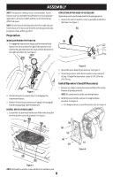
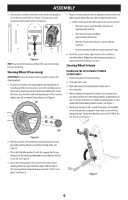
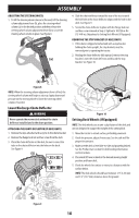
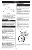
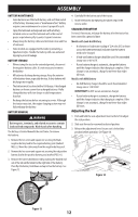
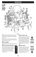
ASSEMBLY ADJUSTING THE STEERING WHEEL 1. To tilt the steering wheel column (a) forward, lift the steering column adjustment lever (b), place the steering wheel column (a) in the desired position and then release the steering wheel column adjustment lever (b) to secure the steering wheel column in place. See Figure 8. (a) 4. Slide the chute deflector toward the rear of the tractor until the bolt hole in the chute deflector aligns with the hole in the deck. See Figure 9. 5. Secure the chute deflector in place with the flange lock nut and hex screw removed in Step 2. Tighten to 102-124 in-lbs (12-14 N-m). Skip ahead to Setting Deck Wheels (If Equipped). REMOVING THE STOP BRACKET (IF NECESSARY) 1. If the chute is shipped attached and with a stop bracket holding the chute upright, the stop brackets must be removed prior to operating the tractor. 2. Holding the chute deflector fully upward, remove the stop bracket. Lower the chute deflector and discard the stop bracket. See Figure 10. (b) Figure 8 NOTE: When the steering column adjustment lever is lifted, the steering wheel column will begin to raise up. Apply downward pressure on the steering wheel to lower the steering wheel column, if needed. Lower Discharge Chute Deflector WARNING Never operate the mower deck without the chute deflector installed and in the down position. ATTACHING THE CHUTE DEFLECTOR (IF NECESSARY) 1. Remove the keys attached with a zip tie to the chute bracket. 2. Remove the flange lock nut and hex screw from the deck. 3. Place the chute deflector on the deck, be sure to insert the tabs on the chute deflector into the holes on the deck. See Figure 9. 5 4 3 Figure 10 Setting Deck Wheels (If Equipped) NOTE: The deck wheels are an anti-scalp feature of the deck and are not designed to support the weight of the cutting deck. 1. Move the tractor to a level surface, preferably pavement. 2. Check tire pressure, adjust if necessary. See tire side wall for proper tire pressure. 3. Make sure the deck is level side-to-side and properly pitched. See the Product Care section for deck leveling information and instructions. 4. Place deck lift lever or knob in the desired mowing height position and lower deck. 5. Check the wheels for contact or excessive clearance with the surface below. NOTE: The deck wheels should have between 1⁄4" (6.35 mm) and 1⁄2" (12.7 mm) clearance above the ground. 5 4 Figure 9 10
-
 1
1 -
2
-
3
-
4
-
 5
5 -
 6
6 -
 7
7 -
 8
8 -
 9
9 -
 10
10 -
 11
11 -
 12
12 -
 13
13 -
 14
14 -
 15
15 -
16
-
17
-
18
-
19
-
20
-
21
-
22
-
23
-
24
-
25
-
26
-
27
-
28
-
29
-
30
-
31
-
32
-
33
-
34
-
35
-
36
-
37
-
38
-
39
-
40
-
41
-
42
-
43
-
44
-
45
-
46
-
47
-
48
-
49
-
50
-
51
-
52
-
53
-
54
-
55
-
56
-
57
-
58
-
59
-
60
-
61
-
62
-
63
-
64
-
65
-
66
-
67
-
68
-
69
-
70
-
71
-
72
-
73
-
74
-
75
-
76
-
77
-
78
-
79
-
80
-
81
-
82
-
83
-
84
-
85
-
86
-
87
-
88
-
89
-
90
-
91
-
92
-
93
-
94
-
95
-
96
 |
 |
