Cub Cadet ZTS1 50 Operation Manual - Page 26
Service
 |
View all Cub Cadet ZTS1 50 manuals
Add to My Manuals
Save this manual to your list of manuals |
Page 26 highlights
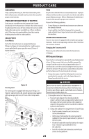
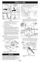
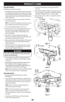
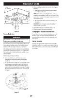
PRODUCT CARE NOTE: Continue to check the front-to-back leveling as you make the side-to-side adjustment as the side-to-side adjustment can affect the front-to-back level. If necessary, adjust front-to-back. 5. When proper adjustment is achieved, re-tighten the jam nuts (b). Tighten to 57 ft-lbs (77 N-m). See Figure 30 on page 25. LEVELING THE DECK (PITCH/FRONT-TO-REAR) The front of the deck should be between 1⁄16-1⁄4" (2-6 mm) lower than the rear of the deck. Adjust if necessary as follows: 1. Park the tractor on a firm, level surface and place the deck lift knob in a middle position. 2. Rotate the blade nearest the discharge chute so that it is parallel with the tractor. 3. Measure the distance from the front of the blade tip to the ground and the rear of the blade tip to the ground. The first measurement taken should be between 1⁄16-1⁄4" (2-6 mm) less than the second measurement. 4. Determine the approximate distance necessary for proper adjustment and proceed, if necessary. 5. To raise the front of the deck, remove the end cap, loosen the outer jam nut (a) then tighten (thread inward) the inner nut (b) against the front hanger bracket. See Figure 31. When proper adjustment is achieved, re-tighten the outer jam nut (a) and replace the end cap. (a) (b) Service ELECTRICAL SYSTEM A fuse is installed to protect the tractor's electrical system from damage caused by excessive amperage. Always use the same capacity fuse for replacement. If the electrical system does not function, check for a blown fuse. If you have a recurring problem with blown fuses, have the tractor's electrical system checked by your authorized service dealer. RELAYS AND SWITCHES There are several safety switches in the electrical system. If a function of the safety interlock system described earlier is not functioning properly, have the electrical system checked by your authorized service dealer. PARK BRAKE ADJUSTMENT If the tractor does not come to a complete stop when the control pedals are in the neutral position, engaging the park brake, or if the tractor's rear wheels can roll with the park brake engaged (and the hydrostatic relief valve open), the brake is in need of adjustment. See your authorized dealer to have the brake properly adjusted. DECK REMOVAL Remove the tractor deck from the tractor as follows: 1. Move the tractor to a level surface, disengage the PTO, stop the engine, place the drive pedals in the neutral position and engage the park brake. 2. There are two methods for removing the belt, to remove the belt by releasing belt tension go on to Step 3, to remove the belt by rolling the belt off the PTO pulley skip ahead to Step 4. Figure 31 6. To lower the front of the deck, remove the end cap, loosen the outer jam nut (a) then loosen (thread outward) the inner nut (b), away from the front hanger bracket. See Figure 31. When proper adjustment is achieved, re-tighten the outer jam nut (a) to 57 ft-lbs (77 N-m) and replace the end cap. ADJUSTING THE DECK WHEELS WARNING Keep hands and feet away from the discharge opening of the cutting deck. NOTE: The deck wheels are an anti-scalp feature of the deck and are not designed to support the weight of the cutting deck. The deck wheels should be approximately 1⁄4-1⁄2" (6.35-12.7 mm) above the ground when the deck is set in the desired height setting. To adjust the deck wheels, see the Assembly section for instructions. WARNING Use caution to avoid pinching your fingers when rolling the belt off the PTO pulley. 3. Releasing belt tension with the idler pulley: a. Using the deck lift pedal and knob, raise the deck to the position that provides the most horizontal run of the belt between the deck idler pulleys and the PTO pulley on the bottom of the engine. See Figure 32 on page 27. b. Working from the middle of the tractor, pivot the idler bracket (a) and movable idler pulley (b) rearward just far enough to lift the belt up and over the spindle pulley. See Figure 32 on page 27. 26
-
 1
1 -
2
-
3
-
4
-
5
-
6
-
7
-
8
-
9
-
10
-
11
-
12
-
13
-
14
-
15
-
16
-
17
-
18
-
19
-
20
-
 21
21 -
 22
22 -
 23
23 -
 24
24 -
 25
25 -
 26
26 -
 27
27 -
 28
28 -
 29
29 -
 30
30 -
 31
31 -
32
-
33
-
34
-
35
-
36
-
37
-
38
-
39
-
40
-
41
-
42
-
43
-
44
-
45
-
46
-
47
-
48
-
49
-
50
-
51
-
52
-
53
-
54
-
55
-
56
-
57
-
58
-
59
-
60
-
61
-
62
-
63
-
64
-
65
-
66
-
67
-
68
-
69
-
70
-
71
-
72
-
73
-
74
-
75
-
76
-
77
-
78
-
79
-
80
-
81
-
82
-
83
-
84
-
85
-
86
-
87
-
88
-
89
-
90
-
91
-
92
-
93
-
94
-
95
-
96
 |
 |