Cub Cadet ZTS1 50 Operation Manual - Page 9
Steering Wheel Column
 |
View all Cub Cadet ZTS1 50 manuals
Add to My Manuals
Save this manual to your list of manuals |
Page 9 highlights
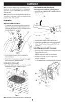
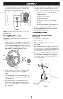
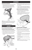
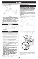
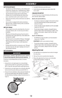
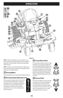
ASSEMBLY 3. If necessary, securely connect the seat switch wiring harness (a) to the seat switch (b). See Figure 5. Secure excess wire away from pinch points before continuing. (b) (b) (a) (a) Figure 5 NOTE: Tractor will not operate without the seat switch wiring harness connected. Steering Wheel (If necessary) IMPORTANT! Do not use impact tools to install or remove the steering wheel. 1. Remove the hardware for attaching the steering wheel (a) from beneath the steering wheel cover (b). Carefully remove the cover by inserting a small, bladed screwdriver into one of the three snap locations and slowly prying up on the steering wheel cover (b) to remove the hardware. See Figure 6. (a) (c) (d) 5. Proper steering column and seat adjustment will result in the following (to adjust the seat, refer to Adjusting the Seat): a. In the neutral position with hands on the steering wheel: • Operator's upper arms should be relaxed and approximately vertical. • Operator's forearms should be approximately horizontal. • Operator's back should stay in contact with the seat back. • Steering column should not contact operator's legs. 6. Check the results of any adjustments to the conditions described above. Repeat any adjustment procedures as required until all conditions are met. Steering Wheel Column INSTALLING THE TILT LOCKING CYLINDER (IF NECESSARY) 1. Remove hardware from manual bag. 2. Sit in operator's seat. 3. With one hand, lift steering wheel column into a raised position. 4. While holding steering wheel column in a raised position, use other hand to raise tilt locking cylinder, aligning holes in top of cylinder with holes in cylinder mounting plates on the underside of the steering wheel column. See Figure 7. 5. Working from right to left, install flat washer and shoulder screw through holes aligned in Step 4 and secure with hex flange lock nut. Torque the shoulder screw to 120-144 in-lbs (14-16 N-m). See Figure 7. (b) Figure 6 2. With the wheels of the machine pointing straight forward, place the steering wheel (a) over the steering shaft. See Figure 6. 3. Place the Belleville washer (c) with the cupped side facing inward over the steering wheel and secure with the hex lock screw (d). See Figure 6. 4. Place the steering wheel cover (b) over the center of the steering wheel (a), align the three snaps with the tabs in the steering wheel and push downward until it "clicks" into place. See Figure 6. Figure 7 9
-
 1
1 -
2
-
3
-
 4
4 -
 5
5 -
 6
6 -
 7
7 -
 8
8 -
 9
9 -
 10
10 -
 11
11 -
 12
12 -
 13
13 -
 14
14 -
15
-
16
-
17
-
18
-
19
-
20
-
21
-
22
-
23
-
24
-
25
-
26
-
27
-
28
-
29
-
30
-
31
-
32
-
33
-
34
-
35
-
36
-
37
-
38
-
39
-
40
-
41
-
42
-
43
-
44
-
45
-
46
-
47
-
48
-
49
-
50
-
51
-
52
-
53
-
54
-
55
-
56
-
57
-
58
-
59
-
60
-
61
-
62
-
63
-
64
-
65
-
66
-
67
-
68
-
69
-
70
-
71
-
72
-
73
-
74
-
75
-
76
-
77
-
78
-
79
-
80
-
81
-
82
-
83
-
84
-
85
-
86
-
87
-
88
-
89
-
90
-
91
-
92
-
93
-
94
-
95
-
96
 |
 |
