D-Link DIS-200G User Manual - Page 10
Top Panel Components, Switch Ground, Terminal Block
 |
View all D-Link DIS-200G manuals
Add to My Manuals
Save this manual to your list of manuals |
Page 10 highlights
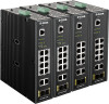
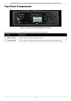
DIS-200G Series Layer 2 Gigabit Industrial Smart Managed Switch Hardware Installation Guide Top Panel Components Figure 1-3 Top panel view of the DIS-200G Series switches Ports that can be found on the top panel of this switch are listed in the table below. LED Description 1 Switch Ground This is used to connect the switch to ground. 2 Terminal Block This is used to connect the switch to external power sources and an alarm relay. 10
-
 1
1 -
2
-
3
-
4
-
 5
5 -
 6
6 -
 7
7 -
 8
8 -
 9
9 -
 10
10 -
 11
11 -
 12
12 -
 13
13 -
 14
14 -
 15
15 -
16
-
17
-
18
-
19
-
20
-
21
-
22
-
23
-
24
-
25
-
26
-
27
-
28
-
29
-
30
-
31
-
32
-
33
-
34
-
35
-
36
-
37
-
38
-
39
-
40
-
41
-
42
-
43
-
44
-
45
-
46
-
47
 |
 |

DIS-200G Series Layer 2 Gigabit Industrial Smart Managed Switch Hardware Installation Guide
10
Top Panel Components
Figure 1-3 Top panel view of the DIS-200G Series switches
Ports that can be found on the top panel of this switch are listed in the table below.
LED
Description
1
Switch Ground
This is used to connect the switch to ground.
2
Terminal Block
This is used to connect the switch to external power sources and an alarm relay.