D-Link DIS-200G User Manual - Page 18
Connecting to a Power Source, Using the Power Adapter (Optional), Using the Terminal Connections
 |
View all D-Link DIS-200G manuals
Add to My Manuals
Save this manual to your list of manuals |
Page 18 highlights
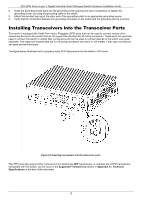
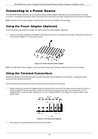
DIS-200G Series Layer 2 Gigabit Industrial Smart Managed Switch Hardware Installation Guide Connecting to a Power Source The.DIS-200G Series switches can be powered using a power adapter (optional) or by using the built-in terminal connector. This allows dual power inputs using wires from the power source(s) screwed into the terminal connections. Note: Inclusion of the power adapter is optional and may not be included in the package. Using the Power Adapter (Optional) Use the following instructions to power the switch using the power adapter (optional): 1. Connect the power adapter (if included) to the power connector on the back of the switch. Connect the other end of the power adapter to a main power source. Figure 2-6 Connecting the power adapter Note: The DIS-200G power adapter can be purchased separately. Please contact your local D-Link reseller. Using the Terminal Connections Before proceeding, ensure that all power sources have been disconnected from the switch, including the power source you are wiring to the switch. Use the following instructions to power the switch using the terminal connections: 1. Before continuing, consult the diagram below to decide which wires from the power source need to connect to which contacts on the terminal block. Note that two power sources can be used; one inserted into V1-/V1+ (labeled PWR 1) and the other inserted into V2-/V2+ (labeled PWR2). This diagram is also provided on the switch itself. Figure 2-7 Terminal block diagram 2. Use a lever to remove the terminal block from the switch. 18
-
 1
1 -
2
-
3
-
4
-
5
-
6
-
7
-
8
-
9
-
10
-
11
-
12
-
 13
13 -
 14
14 -
 15
15 -
 16
16 -
 17
17 -
 18
18 -
 19
19 -
 20
20 -
 21
21 -
 22
22 -
 23
23 -
24
-
25
-
26
-
27
-
28
-
29
-
30
-
31
-
32
-
33
-
34
-
35
-
36
-
37
-
38
-
39
-
40
-
41
-
42
-
43
-
44
-
45
-
46
-
47
 |
 |
