D-Link DIS-200G User Manual - Page 19
Redundant Power Design, connected to PWR 2
 |
View all D-Link DIS-200G manuals
Add to My Manuals
Save this manual to your list of manuals |
Page 19 highlights
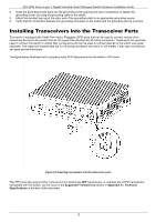
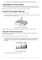
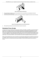
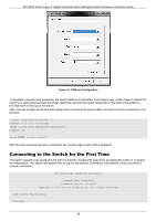
DIS-200G Series Layer 2 Gigabit Industrial Smart Managed Switch Hardware Installation Guide Figure 2-8 Removing the terminal block 3. Using a flat head screwdriver, loosen the connections in the terminal block by unscrewing the terminals connections that you wish to use. 4. Insert the wires into the terminal connections and use the screwdriver to tighten the screws to secure the wires. Figure 2-9 Connecting a power source to the terminal block 5. Re-insert the terminal block into the terminal block socket on the switch. Redundant Power Design A power source can be connected to the power input on the back, and to PWR 1 and PWR 2 on the terminal block at the same time. The power source that is connected first to the switch will automatically be designated as the main power source. Any additional power sources connected afterwards will be designated redundant power sources. When one of the power source is behaving abnormally or fails, the alarm relay and ALM LED will be triggered. There is no order or hierarchy for determining active and redundant power sources. For example, if the first power source is connected to PWR 2, the switch will consider this the main power source. If a power source is then connected to the power input on the back and to PWR 1 on the terminal block, these will be designated as backup power sources. Please note that multiple power sources connected to the switch cannot supply power to the Switch at the same time. For example, when two 120 W power sources are connected to PWR1 and PWR2 on the switch, the switch will only take 120 W power from the power source that was connected first, while the second power source serves as a backup. 19
-
 1
1 -
2
-
3
-
4
-
5
-
6
-
7
-
8
-
9
-
10
-
11
-
12
-
13
-
 14
14 -
 15
15 -
 16
16 -
 17
17 -
 18
18 -
 19
19 -
 20
20 -
 21
21 -
 22
22 -
 23
23 -
 24
24 -
25
-
26
-
27
-
28
-
29
-
30
-
31
-
32
-
33
-
34
-
35
-
36
-
37
-
38
-
39
-
40
-
41
-
42
-
43
-
44
-
45
-
46
-
47
 |
 |
