D-Link DIS-200G User Manual - Page 17
Installing Transceivers into the Transceiver Ports, Supported Transceivers, Appendix A - Technical
 |
View all D-Link DIS-200G manuals
Add to My Manuals
Save this manual to your list of manuals |
Page 17 highlights
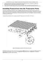
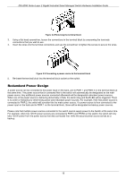
DIS-200G Series Layer 2 Gigabit Industrial Smart Managed Switch Hardware Installation Guide 2. Insert the grounding screw back into the grounding screw opening and use a screwdriver to tighten the grounding screw, securing the grounding cable to the switch. 3. Attach the terminal lug ring at the other end of the grounding cable to an appropriate grounding source. 4. Verify that the connection between the grounding connector on the switch and the grounding source is secure. Installing Transceivers into the Transceiver Ports The switch is equipped with Small Form-factor Pluggable (SFP) ports that can be used to connect various other networking devices to this switch that do not support the standard RJ-45 wiring connection. These ports are generally used to connect this switch to optical fiber connections and can be used to connect devices to the switch over great distances. The maximum distance that the RJ-45 wiring connection can reach is 100 meters. Fiber optic connections can span several kilometers. The figure below illustrates how to properly insert SFP transceivers into the switch's SFP ports. Figure 2-5 Inserting transceivers into the transceiver ports The SFP ports also support other transceiver form factors like SFP transceivers. A complete list of SFP transceivers, compatible with this switch, can be found in the Supported Transceivers section in Appendix A - Technical Specifications at the end of this document. 17
-
 1
1 -
2
-
3
-
4
-
5
-
6
-
7
-
8
-
9
-
10
-
11
-
 12
12 -
 13
13 -
 14
14 -
 15
15 -
 16
16 -
 17
17 -
 18
18 -
 19
19 -
 20
20 -
 21
21 -
 22
22 -
23
-
24
-
25
-
26
-
27
-
28
-
29
-
30
-
31
-
32
-
33
-
34
-
35
-
36
-
37
-
38
-
39
-
40
-
41
-
42
-
43
-
44
-
45
-
46
-
47
 |
 |
