D-Link DIS-200G User Manual - Page 32
Areas of the Web UI, Web s, AREA 1, Tools, Wizard, Online, System, Management, L2 Features
 |
View all D-Link DIS-200G manuals
Add to My Manuals
Save this manual to your list of manuals |
Page 32 highlights
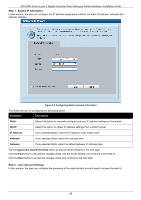
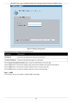
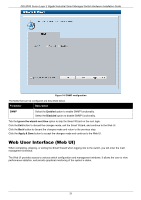
DIS-200G Series Layer 2 Gigabit Industrial Smart Managed Switch Hardware Installation Guide Areas of the Web UI After logging into the switch's Web UI, the following page will be displayed. The Web UI can be divided into three distinct areas that are described in more detail in the table below. Figure 5-5 Main Web UI Window Three main areas are displayed in the window. Area Number Function AREA 1 Select the folder or window to display. Open folders and click the hyperlinked window buttons and subfolders contained within them to display windows. AREA 2 AREA 3 Presents switch status based on user selection and the entry of configuration data. In addition, a hyperlink to Settings is offered to enable quick Gateway configuration. Presents a toolbar used to access function like Save, Tools, the Wizard and Online Help. Web Pages In area 1, mentioned above, the following main folders will be available for selecting. Folder Name Description System Features regarding the switch's configuration can be viewed and configured in this folder. Management Features regarding the switch's management can be viewed and configured in this folder. L2 Features Features regarding the Layer 2 functionality of the switch can be viewed and configured in this folder. 32
-
 1
1 -
2
-
3
-
4
-
5
-
6
-
7
-
8
-
9
-
10
-
11
-
12
-
13
-
14
-
15
-
16
-
17
-
18
-
19
-
20
-
21
-
22
-
23
-
24
-
25
-
26
-
 27
27 -
 28
28 -
 29
29 -
 30
30 -
 31
31 -
 32
32 -
 33
33 -
 34
34 -
 35
35 -
 36
36 -
 37
37 -
38
-
39
-
40
-
41
-
42
-
43
-
44
-
45
-
46
-
47
 |
 |
