Dell G5 5090 Service Manual - Page 52
Installing the system board
 |
View all Dell G5 5090 manuals
Add to My Manuals
Save this manual to your list of manuals |
Page 52 highlights
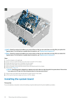
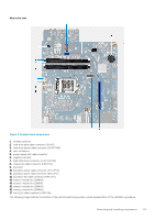
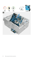
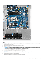
NOTE: Note the routing of all cables as you remove them so that you can route them correctly after you replace the system board. For information on system-board connectors, see "System-board components". NOTE: Note the routing of all cables as you remove them so that you can route them correctly after you replace the system board. For information on system-board connectors, see "System-board components". Steps 1. Lay the computer on the right side. 2. Remove the screw (#6-32) that secures the front I/O-bracket to the chassis. 3. Rotate and remove the front I/O-bracket from the chassis. 4. Disconnect all the cables connected to the system board. 5. Remove the eight screws (#6-32) and that secure the system board to the chassis. 6. Remove the VR heat sink. NOTE: The VR heat sink is shipped as a separate unit and it does not ship along with the system board. Ensure that you replace the VR heat sink from old system board to the new system board. 7. Remove the screw (M2x4) and that secures the system board to the chassis. 8. Lift the system board at an angle and remove it off the chassis. Installing the system board Prerequisites If you are replacing a component, remove the existing component before performing the installation procedure. 52 Removing and installing components
-
 1
1 -
2
-
3
-
4
-
5
-
6
-
7
-
8
-
9
-
10
-
11
-
12
-
13
-
14
-
15
-
16
-
17
-
18
-
19
-
20
-
21
-
22
-
23
-
24
-
25
-
26
-
27
-
28
-
29
-
30
-
31
-
32
-
33
-
34
-
35
-
36
-
37
-
38
-
39
-
40
-
41
-
42
-
43
-
44
-
45
-
46
-
 47
47 -
 48
48 -
 49
49 -
 50
50 -
 51
51 -
 52
52 -
 53
53 -
 54
54 -
 55
55 -
 56
56 -
 57
57 -
58
-
59
-
60
-
61
-
62
-
63
-
64
-
65
-
66
-
67
-
68
-
69
-
70
-
71
-
72
-
73
-
74
-
75
-
76
-
77
-
78
-
79
-
80
 |
 |
