Dell G5 5090 Service Manual - Page 55
For information on system-board connectors, see
 |
View all Dell G5 5090 manuals
Add to My Manuals
Save this manual to your list of manuals |
Page 55 highlights
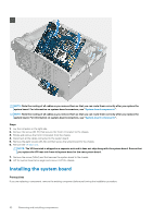
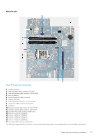
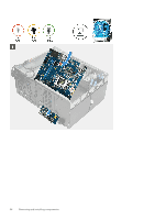
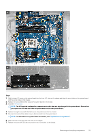
Steps 1. Slide the back I/O-ports on the system board into the front I/O-slots on the chassis and align the screw holes on the system board with the screw holes on the chassis. 2. Replace the screw (M2x4) that secures the system board to the chassis. 3. Install the VR heat sink. NOTE: The VR heat sink is shipped as a separate unit and it does not ship along with the system board. Ensure that you replace the VR heat sink from old system board to the new system board. 4. Replace the eight screws (#6-32) that secure the system board to the chassis. 5. Route and connect all the cables that you disconnected from the system board. NOTE: For information on system-board connectors, see "System-board components". 6. Align the front I/O-bracket with the slots on the chassis. 7. Replace the screw (#6-32) that secures the front I/O-bracket to the chassis. Removing and installing components 55
-
 1
1 -
2
-
3
-
4
-
5
-
6
-
7
-
8
-
9
-
10
-
11
-
12
-
13
-
14
-
15
-
16
-
17
-
18
-
19
-
20
-
21
-
22
-
23
-
24
-
25
-
26
-
27
-
28
-
29
-
30
-
31
-
32
-
33
-
34
-
35
-
36
-
37
-
38
-
39
-
40
-
41
-
42
-
43
-
44
-
45
-
46
-
47
-
48
-
49
-
 50
50 -
 51
51 -
 52
52 -
 53
53 -
 54
54 -
 55
55 -
 56
56 -
 57
57 -
 58
58 -
 59
59 -
 60
60 -
61
-
62
-
63
-
64
-
65
-
66
-
67
-
68
-
69
-
70
-
71
-
72
-
73
-
74
-
75
-
76
-
77
-
78
-
79
-
80
 |
 |
