Dell G5 5090 Service Manual - Page 53
System-board components, processor-fan cable connector FAN CPU
 |
View all Dell G5 5090 manuals
Add to My Manuals
Save this manual to your list of manuals |
Page 53 highlights
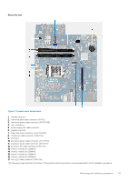
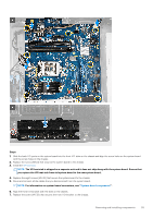
About this task Figure 4. System-board components 1. wireless-card slot 2. hard-drive data cable connector (SATA0) 3. hard-drive power cable connector (SATA PWR) 4. coin-cell battery 5. power-supply unit cable connector 6. graphics-card slot 7. solid-state drive connector (m.2 PCIe SSD) 8. chassis-fan cable connector (FAN SYS) 9. processor 10. processor-power cable connector (ATX CPU1) 11. processor-power cable connector (ATX CPU) 12. processor-fan cable connector (FAN CPU) 13. memory-module slot (DIMM3) 14. memory-module slot (DIMM1) 15. memory-module slot (DIMM4) 16. memory-module slot (DIMM2) 17. front LED cable connector (PWR SW) The following images indicate the location of the system board and provides a visual representation of the installation procedure. Removing and installing components 53
-
 1
1 -
2
-
3
-
4
-
5
-
6
-
7
-
8
-
9
-
10
-
11
-
12
-
13
-
14
-
15
-
16
-
17
-
18
-
19
-
20
-
21
-
22
-
23
-
24
-
25
-
26
-
27
-
28
-
29
-
30
-
31
-
32
-
33
-
34
-
35
-
36
-
37
-
38
-
39
-
40
-
41
-
42
-
43
-
44
-
45
-
46
-
47
-
 48
48 -
 49
49 -
 50
50 -
 51
51 -
 52
52 -
 53
53 -
 54
54 -
 55
55 -
 56
56 -
 57
57 -
 58
58 -
59
-
60
-
61
-
62
-
63
-
64
-
65
-
66
-
67
-
68
-
69
-
70
-
71
-
72
-
73
-
74
-
75
-
76
-
77
-
78
-
79
-
80
 |
 |
