Dell GX260 Service Manual - Page 79
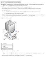
Heat Sink Replacement, pin-1 corners of microprocessor and socket aligned
 |
UPC - 683728163389
View all Dell GX260 manuals
Add to My Manuals
Save this manual to your list of manuals |
Page 79 highlights
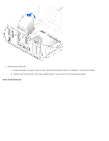
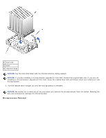
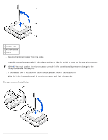
1 pin-1 corners of microprocessor and socket aligned NOTICE: Microprocessor pins are delicate. To avoid damage, ensure that the microprocessor aligns properly with the socket, and do not use excessive force when you install the processor. 9. Carefully set the microprocessor in the socket and press it down lightly to seat it. 10. Rotate the release lever back toward the system board until it snaps into place, securing the microprocessor. 11. Install the heat sink. a. Insert the notched end of the heat sink onto the end of the retention base that is opposite the hinge. b. Lower the heat sink until it fits securely in the base. 12. Raise the retention lever and press until the heat sink is secured. You will feel the lever pause once it is at a 90-degree angle. Keep pressing the lever another 30 degrees, ensuring that it is in the locked position. Heat Sink Replacement 1 heat sink 2 lever 3 hinge 4 retention base 5 notch 13. Lower the airflow shroud over the heat sink. If you installed a microprocessor replacement kit from Dell, return the original heat-sink assembly and microprocessor to Dell in the same package in which your replacement kit was sent. 14. Reconnect the cooling fan power cable to the FAN connector on the system board.
-
 1
1 -
2
-
3
-
4
-
5
-
6
-
7
-
8
-
9
-
10
-
11
-
12
-
13
-
14
-
15
-
16
-
17
-
18
-
19
-
20
-
21
-
22
-
23
-
24
-
25
-
26
-
27
-
28
-
29
-
30
-
31
-
32
-
33
-
34
-
35
-
36
-
37
-
38
-
39
-
40
-
41
-
42
-
43
-
44
-
45
-
46
-
47
-
48
-
49
-
50
-
51
-
52
-
53
-
54
-
55
-
56
-
57
-
58
-
59
-
60
-
61
-
62
-
63
-
64
-
65
-
66
-
67
-
68
-
69
-
70
-
71
-
72
-
73
-
 74
74 -
 75
75 -
 76
76 -
 77
77 -
 78
78 -
 79
79 -
 80
80 -
 81
81 -
 82
82 -
 83
83 -
 84
84 -
85
-
86
-
87
-
88
-
89
-
90
-
91
-
92
-
93
-
94
-
95
-
96
-
97
-
98
-
99
-
100
 |
 |
