Dell OptiPlex 7010 Owner's Manual (Mini-Tower) - Page 33
System Board Components, Installing the System Board, Internal USB 2.0 connector - speaker
 |
View all Dell OptiPlex 7010 manuals
Add to My Manuals
Save this manual to your list of manuals |
Page 33 highlights
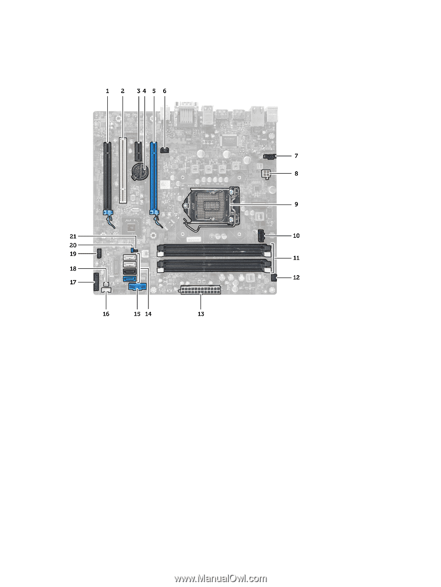
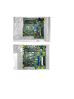
System Board Components Figure 1. Components Of The System Board 1. PCI Express x16 slot (wired as x4) 2. PCI slot 3. PCIe x1 slot 4. Coin-cell battery 5. PCI Express x16 slot 6. Intrusion switch connector 7. System fan connector 8. 4-pin CPU power connecter 9. CPU Socket 10. Heat-sink fan connector 11. DDR DIMM memory slots (4) 12. Front power-button connector 13. ATX 24-pin power connector 14. SATA connectors 15. Front panel USB connector 16. Speaker connector 17. Front panel audio connector 18. Thermal sensor connector 19. Internal USB 2.0 connector 20. Password reset jumper 21. RTCRST jumper connector Installing the System Board 1. Align the system board to the port connectors on the rear of the chassis and place the system board in the chassis. 2. Tighten the screws securing the system board to the chassis. 33
-
 1
1 -
2
-
3
-
4
-
5
-
6
-
7
-
8
-
9
-
10
-
11
-
12
-
13
-
14
-
15
-
16
-
17
-
18
-
19
-
20
-
21
-
22
-
23
-
24
-
25
-
26
-
27
-
 28
28 -
 29
29 -
 30
30 -
 31
31 -
 32
32 -
 33
33 -
 34
34 -
 35
35 -
 36
36 -
 37
37 -
 38
38 -
39
-
40
-
41
-
42
-
43
-
44
-
45
-
46
-
47
-
48
-
49
-
50
-
51
-
52
-
53
-
54
-
55
-
56
-
57
-
58
-
59
-
60
-
61
 |
 |