Dell PowerConnect W-Series FIPS Dell PowerConnect W-600 Controller Series Secu - Page 18
Logical Interfaces, FIPS 140-2 Logical Interfaces, Module Physical Interface
 |
View all Dell PowerConnect W-Series FIPS manuals
Add to My Manuals
Save this manual to your list of manuals |
Page 18 highlights
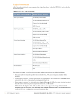
Logical Interfaces All of these physical interfaces are separated into logical interfaces defined by FIPS 140-2, as described in the following table. Table 2 FIPS 140-2 Logical Interfaces FIPS 140-2 Logical Interfaces Module Physical Interface Data Input Interface Data Output Interface Control Input Interface Status Output Interface Power Interface 10/100 Mbps Ethernet Port 10/100/1000 Mbps Ethernet Port Express Card slot (disabled) USB 2.0 ports 10/100 Mbps Ethernet Port 10/100/1000 Mbps Ethernet Port Express Card slot (disabled) USB 2.0 ports 10/100 Mbps Ethernet Port 10/100/1000 Mbps Ethernet Port Express Card slot (disabled) Media Eject Button Serial Console port (disabled) 10/100 Mbps Ethernet port 10/100/1000 Mbps Ethernet ports LEDs Serial Console port (disabled) Power Supply PoE Data input and output, control input, status output, and power interfaces are defined as follows: Data input and output are the packets that use the firewall, VPN, and routing functionality of the modules. Control input consists of manual control inputs for media eject. It also consists of all of the data that is entered into the switch while using the management interfaces. Status output consists of the status indicators displayed through the LEDs, the status data that is output from the switch while using the management interfaces, and the log file. LEDs indicate the physical state of the module, such as power-up (or rebooting), utilization level, activation state (including fan, ports, and power) and status of connected media. The log file records the results of self-tests, configuration errors, and monitoring data. 16 | FIPS 140-2 Level 2 Features Aruba 620, 650 and Dell W-620, W-650 | FIPS 140-2 Level 2 Release Supplement
-
 1
1 -
2
-
3
-
4
-
5
-
6
-
7
-
8
-
9
-
10
-
11
-
12
-
 13
13 -
 14
14 -
 15
15 -
 16
16 -
 17
17 -
 18
18 -
 19
19 -
 20
20 -
 21
21 -
 22
22 -
 23
23 -
24
-
25
-
26
-
27
-
28
-
29
-
30
-
31
-
32
-
33
-
34
-
35
-
36
-
37
-
38
-
39
-
40
-
41
-
42
 |
 |