Dell PowerConnect W-Series FIPS Dell PowerConnect W-600 Controller Series Secu - Page 36
Aruba 650
 |
View all Dell PowerConnect W-Series FIPS manuals
Add to My Manuals
Save this manual to your list of manuals |
Page 36 highlights
Figure 7 Aruba 620 - Bottom view Aruba 650 This sections displays all the TEL locations on the Aruba 650. The Aruba 650 requires a minimum of 6 TELs to be applied as follows: To detect opening of the chassis cover: 1. Spanning the front face plate and left chassis cover 2. Spanning the front face plate and bottom chassis cover 3. Spanning the front face plate and right chassis cover 4. Spanning the right chassis cover and top chassis cover 6. Spanning the left chassis cover and top chassis cover To detect access to restricted ports: 2. Spanning the seriel port 5. Spanning the Express Card slot Figure 8 Aruba 650 - Front view 34 | Installing the Controller Aruba 620, 650 and Dell W-620, W-650 | FIPS 140-2 Level 2 Release Supplement
-
 1
1 -
2
-
3
-
4
-
5
-
6
-
7
-
8
-
9
-
10
-
11
-
12
-
13
-
14
-
15
-
16
-
17
-
18
-
19
-
20
-
21
-
22
-
23
-
24
-
25
-
26
-
27
-
28
-
29
-
30
-
 31
31 -
 32
32 -
 33
33 -
 34
34 -
 35
35 -
 36
36 -
 37
37 -
 38
38 -
 39
39 -
 40
40 -
 41
41 -
42
 |
 |
34
|
Installing the Controller
Aruba 620, 650 and Dell W-620, W-650
|
FIPS 140-2 Level 2 Release Supplement
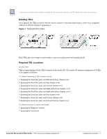
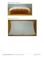
Figure 7
Aruba 620 — Bottom view
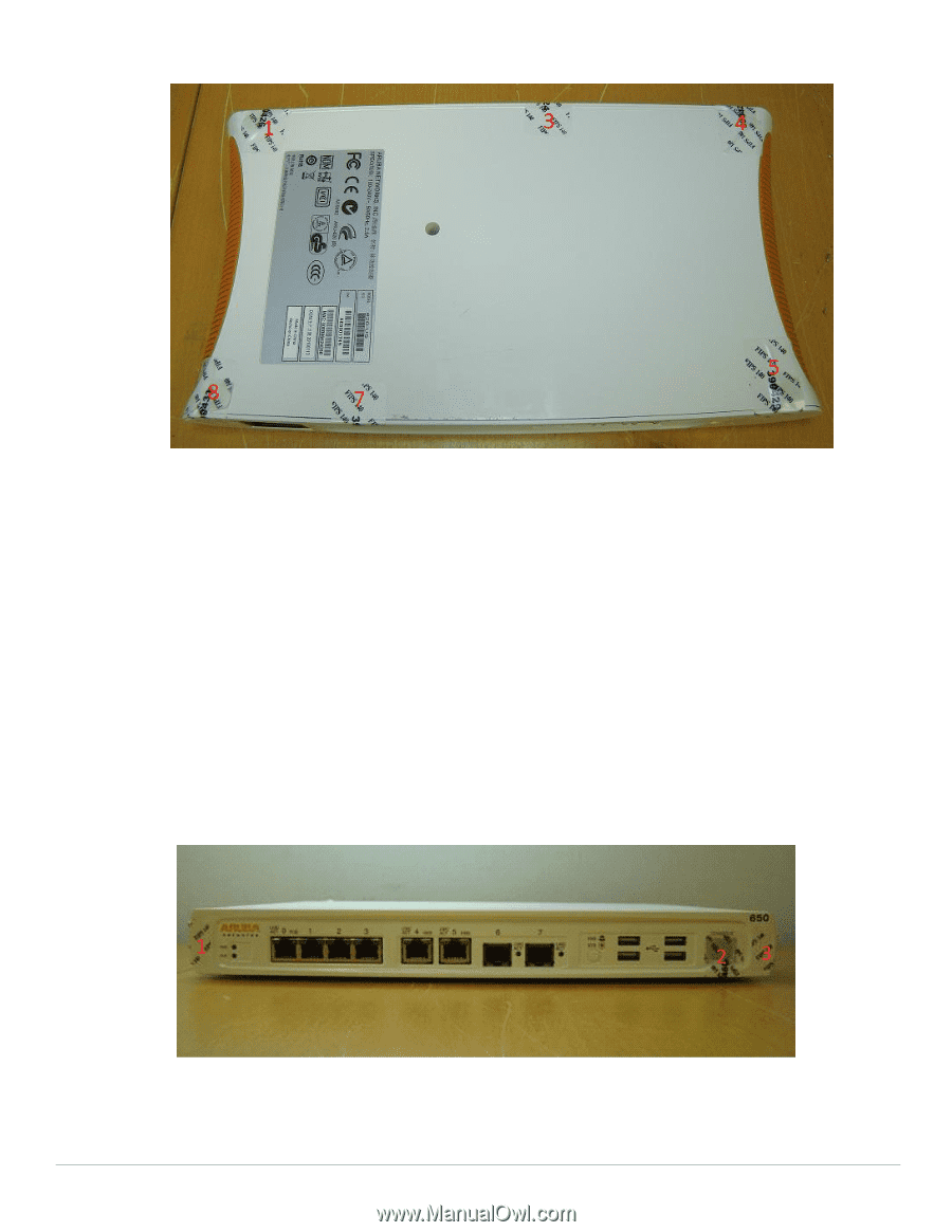
Aruba 650
This sections displays all the TEL locations on the Aruba 650. The Aruba 650 requires a minimum of 6 TELs
to be applied as follows:
To detect opening of the chassis cover:
1. Spanning the front face plate and left chassis cover
2. Spanning the front face plate and bottom chassis cover
3. Spanning the front face plate and right chassis cover
4. Spanning the right chassis cover and top chassis cover
6. Spanning the left chassis cover and top chassis cover
To detect access to restricted ports:
2. Spanning the seriel port
5. Spanning the Express Card slot
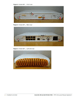
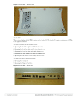
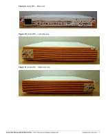
Figure 8
Aruba 650 — Front view