Dell PowerEdge 4350 Dell PowerEdge 4350 System Upgrade Installation Guide
Dell PowerEdge 4350 Manual
 |
View all Dell PowerEdge 4350 manuals
Add to My Manuals
Save this manual to your list of manuals |
Dell PowerEdge 4350 manual content summary:
- Dell PowerEdge 4350 | Dell PowerEdge 4350 System Upgrade Installation Guide - Page 1
™ - Dell PowerEdge 4350 | Dell PowerEdge 4350 System Upgrade Installation Guide - Page 2
this guide, blocks document is subject to change without notice. © 1999 Dell Computer Corporation. All rights reserved. Reproduction in any manner whatsoever without the written permission of Dell Computer Corporation is strictly forbidden. Trademarks used in this text: Dell, PowerEdge, and the DELL - Dell PowerEdge 4350 | Dell PowerEdge 4350 System Upgrade Installation Guide - Page 3
Rack 5 Power Supply Installation 5 Access to the Interior of the System 6 Expansion Card Removal 7 I/O Panel Replacement 9 System Fan Assembly Removal 9 System Cable Removal 11 System Board Removal 11 System Board Installation 13 System Cable Reinstallation 16 Memory - Dell PowerEdge 4350 | Dell PowerEdge 4350 System Upgrade Installation Guide - Page 4
Fan Assembly Removal 10 System Board Removal 12 Dell PowerEdge 6350 System Board Components 13 System Board Jumpers 14 System Board Installation 15 System Cable Connections 17 Power-Supply Paralleling Board (PSPB 18 Diskette and CD-ROM Drive Connections 19 Memory Module 20 PCI Expansion - Dell PowerEdge 4350 | Dell PowerEdge 4350 System Upgrade Installation Guide - Page 5
-card components Associated data and power cables System firmware You also need to upgrade the following components (not included in this kit): Microprocessor(s) Memory Observe the following caution and warnings while servicing this system: Dell PowerEdge 4350 System Upgrade Installation Guide 1 - Dell PowerEdge 4350 | Dell PowerEdge 4350 System Upgrade Installation Guide - Page 6
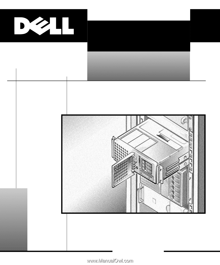
extend the rail into a locking position, and then slide the component into the rack. Do not overload the AC supply branch circuit that provides power to the rack. The total rack load should not exceed 80 percent of the branch circuit rating. 2 Dell PowerEdge 4350 System Upgrade Installation Guide - Dell PowerEdge 4350 | Dell PowerEdge 4350 System Upgrade Installation Guide - Page 7
, you need the following tools: #1 Phillips-head screwdriver #2 Phillips-head screwdriver 1/4" nut driver 3/16" nut driver Small flat-blade screwdriver Needle-nose pliers Use a wrist grounding strap as explained in "Precautionary Measures." Dell PowerEdge 4350 System Upgrade Installation Guide 3 - Dell PowerEdge 4350 | Dell PowerEdge 4350 System Upgrade Installation Guide - Page 8
that might harm internal components. 3. Disconnect your computer and peripherals from their power sources. Also, disconnect any telephone or telecommunication lines from the computer. Doing so reduces the potential for personal injury or shock. 4 Dell PowerEdge 4350 System Upgrade Installation Guide - Dell PowerEdge 4350 | Dell PowerEdge 4350 System Upgrade Installation Guide - Page 9
centimeter (quarter of an inch). b. Rotate the handle back toward the power supply while fitting the two legs of the handle into the slots in the chassis wall, while at the same time pressing the power supply the rest of the way into the bay. Dell PowerEdge 4350 System Upgrade Installation Guide 5 - Dell PowerEdge 4350 | Dell PowerEdge 4350 System Upgrade Installation Guide - Page 10
cards. The right panel door provides access to the expansion slots; the left panel door opens to the processor and memory (see Figure 2). The doors interlock so that the keylock on the right panel door secures both doors and the fan assembly. 6 Dell PowerEdge 4350 System Upgrade Installation Guide - Dell PowerEdge 4350 | Dell PowerEdge 4350 System Upgrade Installation Guide - Page 11
expansion card: a. On the back of the system, press and hold the clip that secures the expansion card that you are removing (see 1 in Figure 3). Dell PowerEdge 4350 System Upgrade Installation Guide 7 - Dell PowerEdge 4350 | Dell PowerEdge 4350 System Upgrade Installation Guide - Page 12
guide to release the latch. - For card guides with a thumb latch, rotate the tab outward (away from the expansion card) to release the latch. 4. Grasp the expansion card by its top corners, and carefully remove it from the expansion-card connector. 8 Dell PowerEdge 4350 System Upgrade Installation - Dell PowerEdge 4350 | Dell PowerEdge 4350 System Upgrade Installation Guide - Page 13
processor(s). Secure the card with two push rivets. To remove the fan assembly, grasp the recessed grip slot at the top of the fan assembly, press in on the release lever inside the slot, and lift the fan assembly from the system (see Figure 4). Dell PowerEdge 4350 System Upgrade Installation Guide - Dell PowerEdge 4350 | Dell PowerEdge 4350 System Upgrade Installation Guide - Page 14
panel. See "SCSI Backplane" in Chapter 4 of the Service Manual for more information. 3. Orient the air dam shroud as shown in Figure 4. 4. Press air dam shroud in to latch it in place. 5. Replace the top-cover panel. 6. Replace the bezel. 10 Dell PowerEdge 4350 System Upgrade Installation Guide - Dell PowerEdge 4350 | Dell PowerEdge 4350 System Upgrade Installation Guide - Page 15
system interface (SCSI) cable from the SCSI backplane connector labeled "SCSI A," and remove it from the system. 5. Disconnect the 50-pin Ultra/Narrow SCSI cable from the CD-ROM drive, and remove and lift it out of the chassis (see Figure 5). Dell PowerEdge 4350 System Upgrade Installation Guide 11 - Dell PowerEdge 4350 | Dell PowerEdge 4350 System Upgrade Installation Guide - Page 16
system board tray center-brace screws (3) center brace thumbscrew system board tray screws (6) 12 Dell PowerEdge 4350 System Upgrade Installation Guide - Dell PowerEdge 4350 | Dell PowerEdge 4350 System Upgrade Installation Guide - Page 17
64-bit PCI connectors (PCI4 through PCI7) To install the new system board, perform the following steps. NOTE: Memory and processors for the PowerEdge 6350 system board are not supplied in the upgrade kit; you must purchase them separately. Dell PowerEdge 4350 System Upgrade Installation Guide 13 - Dell PowerEdge 4350 | Dell PowerEdge 4350 System Upgrade Installation Guide - Page 18
1. Carefully remove the system board from its packaging material. 2. Verify that the jumpers are set as shown in Figure 7 except for the speed jumper, which should be set to the speed of the processor(s). jumpered unjumpered 14 Dell PowerEdge 4350 System Upgrade Installation Guide - Dell PowerEdge 4350 | Dell PowerEdge 4350 System Upgrade Installation Guide - Page 19
on each side). system fan assembly center-brace screws (3) memory module expansion-card connectors center brace memory retention bracket thumbscrew system-board connectors memoryboard connector system board system board tray screws (6) Dell PowerEdge 4350 System Upgrade Installation Guide 15 - Dell PowerEdge 4350 | Dell PowerEdge 4350 System Upgrade Installation Guide - Page 20
the data cable from the CD-ROM drive to the connector labeled "SEC- ONDARY SCSI" on the system board. 4. Connect the 68-pin data cable from the SCSI backplane to the connector labeled "PRIMARY SCSI A" on the system board (see Figure 9). 16 Dell PowerEdge 4350 System Upgrade Installation Guide - Dell PowerEdge 4350 | Dell PowerEdge 4350 System Upgrade Installation Guide - Page 21
"PWR3" in the upgrade kit to connector PWR3 on the PSPB (see Figure 10). 9. Connect the three power cables leading from the PSPB to the power input connectors labeled "POWER1," "POWER2," and "POWER3" on the system board (see Figure 6). Dell PowerEdge 4350 System Upgrade Installation Guide 17 - Dell PowerEdge 4350 | Dell PowerEdge 4350 System Upgrade Installation Guide - Page 22
to the chassis intrusion switch connector labeled "INTRUS2." b. The flat data cable from the hot-plug PCI card connects to the connector labeled "PCILEDPNL." c. The external SCSI data cable attaches to the connector labeled "PRIMARY SCSI-B." 18 Dell PowerEdge 4350 System Upgrade Installation Guide - Dell PowerEdge 4350 | Dell PowerEdge 4350 System Upgrade Installation Guide - Page 23
8): a. Position the brace in the chassis. b. Fasten it with two screws on the right side and one screw on the left side of the chassis. Dell PowerEdge 4350 System Upgrade Installation Guide 19 - Dell PowerEdge 4350 | Dell PowerEdge 4350 System Upgrade Installation Guide - Page 24
banks. For more information on installing memory, refer to "Adding Memory" in Chapter 8 of the system's Installation and Troubleshooting Guide. bank 4 bank 3 bank 2 bank fan assembly must be flush with or below the adjacent panel doors. 20 Dell PowerEdge 4350 System Upgrade Installation Guide - Dell PowerEdge 4350 | Dell PowerEdge 4350 System Upgrade Installation Guide - Page 25
-card connectors-three 32-bit slots and four 64-bit slots (see Figure 14). Connectors PCI1 through PCI3 support 32-bit PCI cards, and PCI4 through PCI7 support 32-bit and 64-bit PCI cards. All slots support full-length expansion cards. Dell PowerEdge 4350 System Upgrade Installation Guide 21 - Dell PowerEdge 4350 | Dell PowerEdge 4350 System Upgrade Installation Guide - Page 26
install an expansion card, perform the following steps. 1. Select the expansion slot in which you will install the new expansion card. 2. Insert the card-edge connector firmly into the expansion-card connector on the chassis (see Figure 15). 22 Dell PowerEdge 4350 System Upgrade Installation Guide - Dell PowerEdge 4350 | Dell PowerEdge 4350 System Upgrade Installation Guide - Page 27
card guide (thumb latch type) expansion card release tab expansion card latch 3. When the card is firmly seated in the connector brackets also keep dust and dirt out of the computer and aid in proper cooling and airflow inside the computer. Dell PowerEdge 4350 System Upgrade Installation Guide 23 - Dell PowerEdge 4350 | Dell PowerEdge 4350 System Upgrade Installation Guide - Page 28
Install the memory and processor information label the system badge on the front bezel of the computer, edge of the badge. 2. Insert a small flat-blade screwdriver under the top edge Guide for more information. 3. Slide the system into the rack. 24 Dell PowerEdge 4350 System Upgrade Installation Guide - Dell PowerEdge 4350 | Dell PowerEdge 4350 System Upgrade Installation Guide - Page 29
the Dell Server Assistant CD," in the system's User's Guide. 9. Run the Resource Configuration Utility to save the new configuration to the system board. If your original PowerEdge 4350 system was a single-processor system and the upgraded system has two or more processors, you must upgrade your - Dell PowerEdge 4350 | Dell PowerEdge 4350 System Upgrade Installation Guide - Page 30
system, perform the following steps to update the system: 1. At the server console, type nwconfig. 2. Select MULTI CPU OPTIONS. 3. Select SELECT A PLATFORM SUPPORT MODULE. 4. Select MPS14.PSM. 5. Down the server. 6. Restart the server. 26 Dell PowerEdge 4350 System Upgrade Installation Guide - Dell PowerEdge 4350 | Dell PowerEdge 4350 System Upgrade Installation Guide - Page 31
with installed processor(s) and memory System board tray Two SCSI cables Two DC power cables I/O panel External SCSI port filler bracket Air dam shroud (if one was previously installed) Two screws You do not need to return these parts to Dell. Dell PowerEdge 4350 System Upgrade Installation Guide 27 - Dell PowerEdge 4350 | Dell PowerEdge 4350 System Upgrade Installation Guide - Page 32
28 Dell PowerEdge 4350 System Upgrade Installation Guide - Dell PowerEdge 4350 | Dell PowerEdge 4350 System Upgrade Installation Guide - Page 33
- Dell PowerEdge 4350 | Dell PowerEdge 4350 System Upgrade Installation Guide - Page 34
™
-
 1
1 -
 2
2 -
 3
3 -
 4
4 -
 5
5 -
 6
6 -
 7
7 -
8
-
9
-
10
-
11
-
12
-
13
-
14
-
15
-
16
-
17
-
18
-
19
-
20
-
21
-
22
-
23
-
24
-
25
-
26
-
27
-
28
-
29
-
30
-
31
-
32
-
33
-
34
 |
 |
ZZZ±GHOO±FRP
™
’HOO±²3RZHU(GJH±²³´µ
²6\VWHP²8SJUDGH
,167$//$7,21²*8,’(