Dell PowerEdge 4350 Dell PowerEdge 4350 System Upgrade Installation Guide - Page 15
Vwhp²&deoh²5hprydo, Vwhp²%rdug²5hprydo²
 |
View all Dell PowerEdge 4350 manuals
Add to My Manuals
Save this manual to your list of manuals |
Page 15 highlights
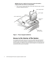
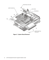
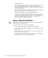
To remove the system cables, perform the following steps: 1. Remove the center brace. The center brace is secured by two screws on the right side of the chassis and one screw on the left, and both ends of the brace are hooked into the chassis walls. Remove the screws and work the brace up out of the chassis (see Figure 5). 2. Disconnect all internal cables from the system board. Place the cable ends out of the way. 3. Disconnect the cables labeled "POWER1" and "POWER2" from the powersupply paralleling board (PSPB) (see Figure 9), and remove them from the system. 4. Disconnect the 68-pin Ultra2/low voltage differential (LVD) small computer system interface (SCSI) cable from the SCSI backplane connector labeled "SCSI A," and remove it from the system. 5. Disconnect the 50-pin Ultra/Narrow SCSI cable from the CD-ROM drive, and remove it from the system. To remove the system board from the chassis, perform the following steps: 1. Remove the six screws that hold the system board tray to the bottom of the chassis (three screws on each side). 2. Lift up slightly on the system board tray. 3. Tilt the system board tray up toward the right side of the chassis and lift it out of the chassis (see Figure 5). Dell PowerEdge 4350 System Upgrade Installation Guide 11
-
 1
1 -
2
-
3
-
4
-
5
-
6
-
7
-
8
-
9
-
 10
10 -
 11
11 -
 12
12 -
 13
13 -
 14
14 -
 15
15 -
 16
16 -
 17
17 -
 18
18 -
 19
19 -
 20
20 -
21
-
22
-
23
-
24
-
25
-
26
-
27
-
28
-
29
-
30
-
31
-
32
-
33
-
34
 |
 |
