Dell PowerEdge 4350 Dell PowerEdge 4350 System Upgrade Installation Guide - Page 21
Ultra2/LVD SCSI host adapter
 |
View all Dell PowerEdge 4350 manuals
Add to My Manuals
Save this manual to your list of manuals |
Page 21 highlights
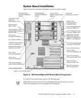
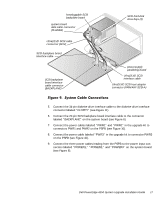
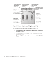
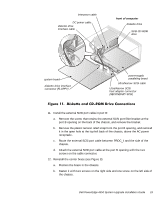
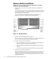
hot-pluggable SCSI backplane board system board data cable connector (PLANAR) Ultra2/LVD SCSI cable connector (SCSI) SCSI backplane board interface cable SCSI backplane board interface cable connector (BACKPLANE) SCSI hard-disk drive bays (3) power-supply paralleling board Ultra2/LVD SCSI interface cable Ultra2/LVD SCSI host adapter connector (PRIMARY SCSI-A) 5. Connect the 34-pin diskette-drive interface cable to the diskette-drive interface connector labeled "FLOPPY" (see Figure 11). 6. Connect the 20-pin SCSI backplane board interface cable to the connector labeled "BACKPLANE" on the system board (see Figure 6). 7. Connect the power cables labeled "PWR1" and "PWR2" in the upgrade kit to connectors PWR1 and PWR2 on the PSPB (see Figure 10). 8. Connect the power cable labeled "PWR3" in the upgrade kit to connector PWR3 on the PSPB (see Figure 10). 9. Connect the three power cables leading from the PSPB to the power input connectors labeled "POWER1," "POWER2," and "POWER3" on the system board (see Figure 6). Dell PowerEdge 4350 System Upgrade Installation Guide 17
-
 1
1 -
2
-
3
-
4
-
5
-
6
-
7
-
8
-
9
-
10
-
11
-
12
-
13
-
14
-
15
-
 16
16 -
 17
17 -
 18
18 -
 19
19 -
 20
20 -
 21
21 -
 22
22 -
 23
23 -
 24
24 -
 25
25 -
 26
26 -
27
-
28
-
29
-
30
-
31
-
32
-
33
-
34
 |
 |
