Dell PowerEdge 4350 Dell PowerEdge 4350 System Upgrade Installation Guide - Page 13
Vwhp²dq²$vvhpeo\²5hprydo
 |
View all Dell PowerEdge 4350 manuals
Add to My Manuals
Save this manual to your list of manuals |
Page 13 highlights
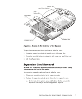
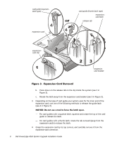
To replace the input/output (I/O) panel, perform the following steps: 1. Remove any remaining expansion slot fillers. 2. Remove the seven screws that hold the I/O panel to the chassis. Two screws are located on the right side of the computer; five are located on the back. 3. Lift off the I/O panel. 4. Position the new I/O panel on the chassis. 5. Replace the two screws on the side and four screws on the back. The remaining screw is not used. Expansion slot filler panels are replaced when you reinstall the expansion cards. 6. Install the hot-plug PCI indicator card: a. Place the hot-plug PCI gasket on the hot-plug PCI indicator so that the light- emitting diodes (LEDs) show through the holes in the gasket. b. Position the card on the I/O panel so that the two holes in the card are aligned with the corresponding holes in the panel. The end of the card with the ribbon cable attached should be nearest to the processor(s). Secure the card with two push rivets. To remove the fan assembly, grasp the recessed grip slot at the top of the fan assembly, press in on the release lever inside the slot, and lift the fan assembly from the system (see Figure 4). Dell PowerEdge 4350 System Upgrade Installation Guide 9
-
 1
1 -
2
-
3
-
4
-
5
-
6
-
7
-
 8
8 -
 9
9 -
 10
10 -
 11
11 -
 12
12 -
 13
13 -
 14
14 -
 15
15 -
 16
16 -
 17
17 -
 18
18 -
19
-
20
-
21
-
22
-
23
-
24
-
25
-
26
-
27
-
28
-
29
-
30
-
31
-
32
-
33
-
34
 |
 |
