Dell PowerEdge 4350 Dell PowerEdge 4350 System Upgrade Installation Guide - Page 20
Installation and Troubleshooting Guide
 |
View all Dell PowerEdge 4350 manuals
Add to My Manuals
Save this manual to your list of manuals |
Page 20 highlights
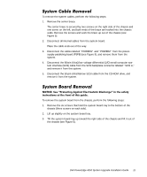
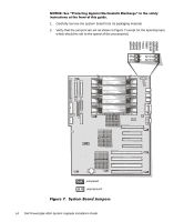
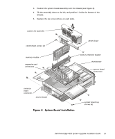
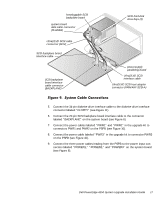
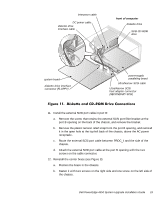
6. Install the processor(s). The processors are supplied separately from the system upgrade kit. For information on installing a processor, refer to "Upgrading the Microprocessor or Installing an Additional Microprocessor" in Chapter 8 of the system's Installation and Troubleshooting Guide. When you install the processor(s), verify that all of them are the same speed, and verify that the speed jumper is set to this speed (see Figure 7). 7. Install terminator cartridges in any unoccupied processor sockets. The terminator cartridges are supplied separately from the system upgrade kit. For information on installing a terminator cartridge, refer to "Upgrading the Microprocessor or Installing an Additional Microprocessor" in Chapter 8 of the system's Installation and Troubleshooting Guide. NOTE: The system cables that are routed underneath the system fan assembly are labeled for their correct installation order. To reinstall the system cables, perform the following steps: 1. Connect the 50-pin data cable in the upgrade kit to the CD-ROM drive. 2. Connect the 68-pin data cable in the upgrade kit to the SCSI backplane connector labeled "SCSI A." 3. Connect the data cable from the CD-ROM drive to the connector labeled "SEC- ONDARY SCSI" on the system board. 4. Connect the 68-pin data cable from the SCSI backplane to the connector labeled "PRIMARY SCSI A" on the system board (see Figure 9). 16 Dell PowerEdge 4350 System Upgrade Installation Guide
-
 1
1 -
2
-
3
-
4
-
5
-
6
-
7
-
8
-
9
-
10
-
11
-
12
-
13
-
14
-
 15
15 -
 16
16 -
 17
17 -
 18
18 -
 19
19 -
 20
20 -
 21
21 -
 22
22 -
 23
23 -
 24
24 -
 25
25 -
26
-
27
-
28
-
29
-
30
-
31
-
32
-
33
-
34
 |
 |