Dell Precision R7610 Dell Precision Workstation R7610 Owner's Manual - Page 11
System Overview
 |
View all Dell Precision R7610 manuals
Add to My Manuals
Save this manual to your list of manuals |
Page 11 highlights
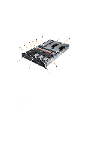
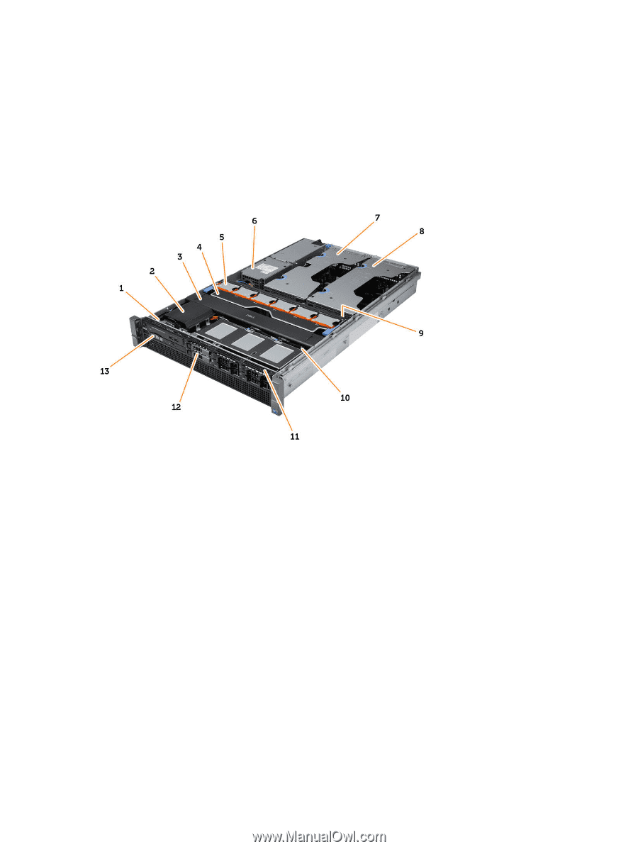
2 System Overview The figure below displays the inside view of the computer after the front bezel and the cover have been removed. The callouts show the names and the layout of the components inside the computer. 1. control panel 2. plastic cover 3. cooling shroud 4. fan bracket 5. system fans 6. power distribution unit 7. center expansion-card cage 8. outer expansion-card cage 9. coin-cell battery 10. SAS back plane 11. front-chassis assembly 12. hard drive 13. optical drive 11
-
 1
1 -
2
-
3
-
4
-
5
-
 6
6 -
 7
7 -
 8
8 -
 9
9 -
 10
10 -
 11
11 -
 12
12 -
 13
13 -
 14
14 -
 15
15 -
 16
16 -
17
-
18
-
19
-
20
-
21
-
22
-
23
-
24
-
25
-
26
-
27
-
28
-
29
-
30
-
31
-
32
-
33
-
34
-
35
-
36
-
37
-
38
-
39
-
40
-
41
-
42
-
43
-
44
-
45
-
46
-
47
-
48
-
49
-
50
-
51
-
52
-
53
-
54
-
55
-
56
-
57
-
58
-
59
-
60
-
61
-
62
-
63
-
64
-
65
-
66
-
67
-
68
-
69
-
70
-
71
-
72
-
73
-
74
-
75
-
76
-
77
-
78
-
79
-
80
-
81
-
82
-
83
-
84
-
85
-
86
-
87
-
88
-
89
-
90
-
91
-
92
-
93
-
94
-
95
-
96
-
97
-
98
-
99
-
100
-
101
-
102
-
103
-
104
-
105
-
106
-
107
-
108
-
109
-
110
-
111
-
112
-
113
-
114
-
115
-
116
-
117
-
118
-
119
-
120
-
121
-
122
-
123
 |
 |
2
System Overview
The figure below displays the inside view of the computer after the front bezel and the cover have been removed. The
callouts show the names and the layout of the components inside the computer.
1. control panel
2. plastic cover
3. cooling shroud
4. fan bracket
5. system fans
6. power distribution unit
7. center expansion-card cage
8. outer expansion-card cage
9. coin-cell battery
10. SAS back plane
11. front-chassis assembly
12. hard drive
13. optical drive
11