Dell S4112F EMC S4112–ON Series Installation Guide October 2021 - Page 12
Prerequisite, S4112–ON Series configurations
 |
View all Dell S4112F manuals
Add to My Manuals
Save this manual to your list of manuals |
Page 12 highlights
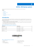
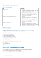
NOTE: There are four LEDs for each QSFP28 port. For each port, 100GbE or 40GbE uses only one LED, 2x50GbE uses two LEDs, and 4x25GbE or 4x10GbE uses all four LEDs. Table 5. QSFP28 port LEDs LED Link/Activity LED Link/Activity LED-4x25G mode or 4x10G mode Link/Activity LED-2x50G Description ● Off-No link ● Solid green-Port link operating at maximum speed-100G on a QSFP28 port or 40G on a QSFP+ port ● Flashing green-Port activity operating at maximum speed -100G on a QSFP28 port ● Solid yellow-Port link operating at a lower speed ● Flashing yellow, 1 second on/off-Port beacon-Port activity at 100G on a QSFP28 port ● Off-No link ● Solid green-Port link at 4x25G on a QSFP28 port or 4x10G on a QSFP+ port ● Flashing green-Port activity at 4x25G on a QSFP28 port ● Solid yellow-Port link at 4x10G on a QSFP28 port ● Flashing yellow, 1 second on/off-Port beacon-Port activity at 4x10G on a QSFP28 port ● Off-No link ● Solid yellow-Port link at 2x50G on a QSFP28 port ● Flashing yellow-Port activity at 2x50G on a QSFP28 port ● Flashing yellow, 1 second on/off-Port beacon Prerequisite NOTE: For detailed installation instructions, see Site preparations and S4112-ON Series installation sections. The following is a list of required and optional components for the S4112-ON Series switch: ● S4112F-ON or S4112T-ON switch ● AC country- and regional-specific cables to connect the AC power source to each of the switches' AC power supplies ● Metal wire clips for AC power cables ● Dual tray or single rails, not included ● Screws for rack installation, not included ● #1 and #2 Phillips screwdrivers, not included ● Torx screwdriver, not included ● Ground cable screws, included ● Copper or fiber cables Other optional components are: ● AC or DC ground cable for the frame-end of the ground cable ● AC ground lug ● Extra power supply unit NOTE: The DC ground lug kit ships with the other accessories inside the shipping box. S4112-ON Series configurations The S4112-ON Series (S4112F-ON and S4112T-ON) switch is available in several different configurations. All S4112-ON Series switches include the following configurations: ● AC power supply with airflow from the I/O side to the PSU side-normal 12 S4112-ON Series switch
-
 1
1 -
2
-
3
-
4
-
5
-
6
-
 7
7 -
 8
8 -
 9
9 -
 10
10 -
 11
11 -
 12
12 -
 13
13 -
 14
14 -
 15
15 -
 16
16 -
 17
17 -
18
-
19
-
20
-
21
-
22
-
23
-
24
-
25
-
26
-
27
-
28
-
29
-
30
-
31
-
32
-
33
-
34
-
35
-
36
-
37
-
38
-
39
-
40
-
41
-
42
 |
 |
