Dell S4112F EMC S4112–ON Series Installation Guide October 2021 - Page 25
After switch installation, Switch replacement, Power up sequence
 |
View all Dell S4112F manuals
Add to My Manuals
Save this manual to your list of manuals |
Page 25 highlights
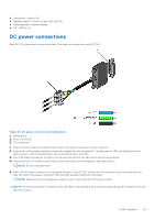
● All protective covers are in place. ● Blank panels are installed if you do not install optional modules. NOTE: A US AC power cable is included for powering up an AC power supply. You must order all other power cables separately. NOTE: ESD damage can occur if components are mishandled. Always wear an ESD-preventive wrist or heel ground strap when handling the S4112-ON Series switch and its components. Power up sequence When the switch powers up, the fans immediately come on at high speed. The fan speed slows as the switch continues to boot up. After switch installation After you have securely installed and powered on the S4112-ON Series switch: ● If you are using Dell EMC software, see switch documentation at www.dell.com/support. ● If you need ONIE information, see ONIE documentation at www.onie.org. ● If you are using third-party software, see your third-party documentation. Switch replacement The following steps describe removing and replacing a switch. For further assistance when replacing a switch, contact your Dell EMC support representative. NOTE: ESD damage can occur when components are mishandled. Always wear an ESD-preventive wrist or heel ground strap when handling the switch and accessories. After you remove the original packaging, place the switch and components on an anti-static surface. 1. Back up the switch configuration to your back-up computer or laptop TFTP server. copy running-config tftp://hostip/filepath To establish a console connection to the switch CLI, assign an IP address on the switch network. 2. Disconnect the power source. 3. Label and remove all cables. 4. Remove the switch from the dual tray. Press the front switch latch according to the arrow and slide the switch forward. If you are using the PSUs in the replacement switch, remove them from the switch. 5. Unpack the new switch. For more information, see Unpack. 6. Confirm that the software version of the replacement switch is the same as the previously installed switch. show os-version If the software versions do not match, upgrade the replacement switch software using the procedure included with the firmware download. 7. Copy the backed-up switch configuration to the new switch. copy tftp://hostip/filepath running-config 8. Install the new switch in the dual tray. For detailed installation instructions, see S4112-ON Series installation. If you are using the PSUs from the removed switch, reinsert them in the replacement switch. 9. Connect all the cables. 10. Power on the switch. S4112-ON Series installation 25
-
 1
1 -
2
-
3
-
4
-
5
-
6
-
7
-
8
-
9
-
10
-
11
-
12
-
13
-
14
-
15
-
16
-
17
-
18
-
19
-
 20
20 -
 21
21 -
 22
22 -
 23
23 -
 24
24 -
 25
25 -
 26
26 -
 27
27 -
 28
28 -
 29
29 -
 30
30 -
31
-
32
-
33
-
34
-
35
-
36
-
37
-
38
-
39
-
40
-
41
-
42
 |
 |
