Dell S4112F EMC S4112–ON Series Installation Guide October 2021 - Page 17
Rack mounting, Switch ground, Fans and airflow, Fan combinations
 |
View all Dell S4112F manuals
Add to My Manuals
Save this manual to your list of manuals |
Page 17 highlights
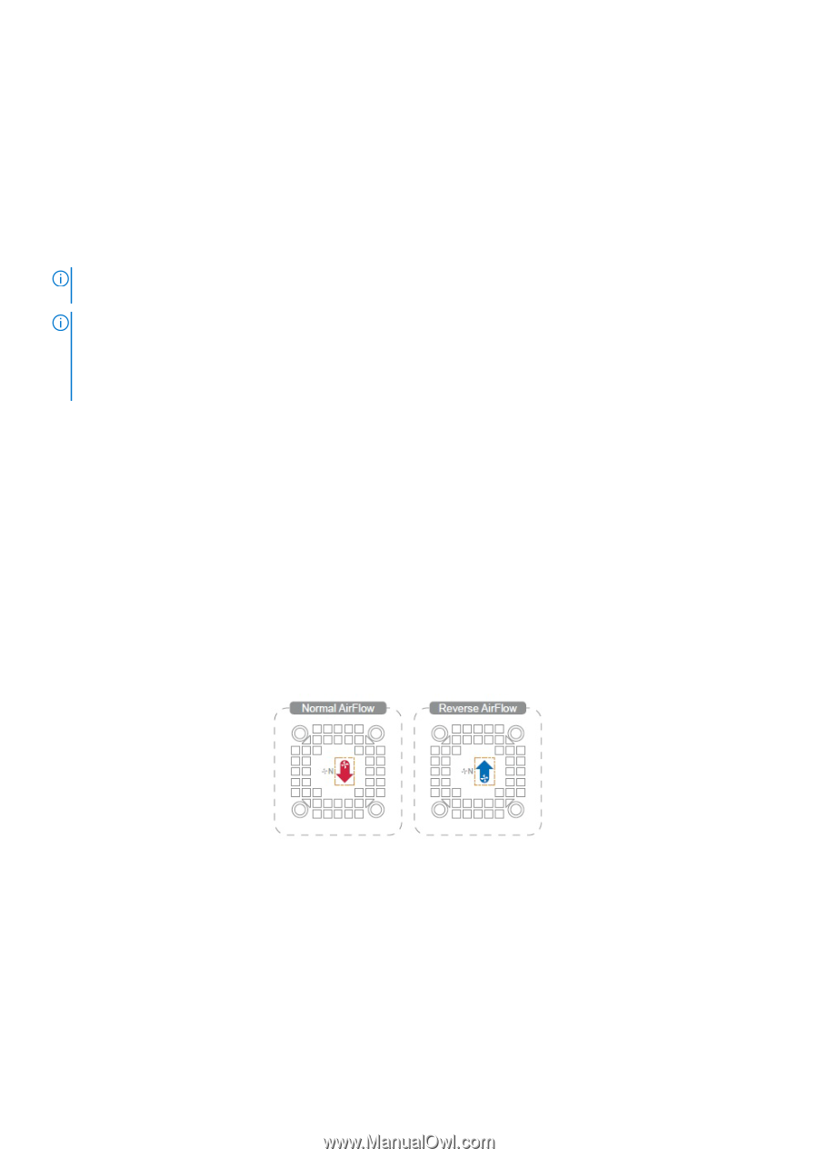
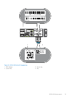
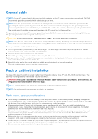
Rack mounting When you prepare your equipment rack, ensure that the rack is grounded. Ground the equipment rack to the same ground point the power service in your area uses. The ground path must be permanent. Switch ground Dell EMC recommends grounding your switch. Use the S4112-ON Series switch in a CBN. NOTE: For an AC-powered switch, although the third conductor of the AC power cord provides a ground path, Dell EMC recommends grounding your switch with a dedicated ground wire. NOTE: For a DC-powered switch, the only way to safely ground your switch is to attach a dedicated ground wire. The ground lug kit ships in a plastic bag placed with the other accessories inside the shipping box. The ground lug bracket screws ship attached to the switch. Before you install the DC switch in the dual-tray, attach the ground lug and bracket to the switch using the included screws and then attach the DC ground wire to the ground lug. The DC-powered switch ships with the DC ground lug, bracket, and screws. For more information, see Ground cable. Fans and airflow The fans on the S4112-ON Series (S4112F-ON and S4112T-ON) switch support two airflow options: normal and reverse. Fan combinations Fan installation is done as part of the factory install based on SKU type. The S4112-ON Series has stock keeping units (SKUs) that support the following configurations: ● AC PSU and system fans normal airflow ● AC PSU and system fans reverse airflow ● DC PSU and system fans normal airflow ● DC PSU and system fans reverse airflow Figure 11. Fan airflow ● Red down arrow shows hot airflow out. ● Blue up arrow shows cold airflow in. For proper ventilation, position the switch in an equipment rack or cabinet with a minimum of 5 inches (12.7 cm) of clearance around the exhaust vents. When you install two S4112-ON Series switches near each other, to permit proper airflow, position the two switches at least 5 inches (12.7 cm) apart. The fan speed varies based on internal temperature monitoring. The S4112- ON Series never intentionally turns off the fans. For more information, see Fans. Site preparations 17
-
 1
1 -
2
-
3
-
4
-
5
-
6
-
7
-
8
-
9
-
10
-
11
-
 12
12 -
 13
13 -
 14
14 -
 15
15 -
 16
16 -
 17
17 -
 18
18 -
 19
19 -
 20
20 -
 21
21 -
 22
22 -
23
-
24
-
25
-
26
-
27
-
28
-
29
-
30
-
31
-
32
-
33
-
34
-
35
-
36
-
37
-
38
-
39
-
40
-
41
-
42
 |
 |