Dell S4112F EMC S4112–ON Series Installation Guide October 2021 - Page 28
AC power cable clips, PSU LEDs, S4112T-ON AC PSUs, AC power cable clips
 |
View all Dell S4112F manuals
Add to My Manuals
Save this manual to your list of manuals |
Page 28 highlights
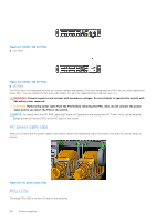
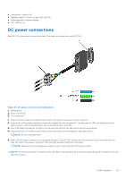
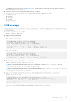
Figure 23. S4112T-ON AC PSUs 1. AC PSUs Figure 24. S4112T-ON DC PSUs 1. DC PSUs The PSUs have an integrated fan that you cannot replace individually; if the fans integrated in a PSU fail, you must replace the entire PSU. You can replace the fan trays individually. For fan tray replacement procedures, see Fans. WARNING: Prevent exposure and contact with hazardous voltages. Do not attempt to operate this switch with the safety cover removed. CAUTION: Remove the power cable from the PSU before removing the PSU. Also, do not connect the power cable before you insert the PSU in the switch. NOTE: To comply with the GR-1089 Lightning Criteria for Equipment Interfacing with AC Power Ports, use an external surge protection device (SPD) at the AC input of the router. AC power cable clips After you connect the AC power cable to the switch, attach the metal wire clip to the switch over each AC power cable, as shown. Figure 25. AC power cable clips PSU LEDs The single PSU LED is on the I/O-side of the switches. 28 Power supplies
-
 1
1 -
2
-
3
-
4
-
5
-
6
-
7
-
8
-
9
-
10
-
11
-
12
-
13
-
14
-
15
-
16
-
17
-
18
-
19
-
20
-
21
-
22
-
 23
23 -
 24
24 -
 25
25 -
 26
26 -
 27
27 -
 28
28 -
 29
29 -
 30
30 -
 31
31 -
 32
32 -
 33
33 -
34
-
35
-
36
-
37
-
38
-
39
-
40
-
41
-
42
 |
 |
