Dell S4112F EMC S4112–ON Series Installation Guide October 2021 - Page 29
DC power connections
 |
View all Dell S4112F manuals
Add to My Manuals
Save this manual to your list of manuals |
Page 29 highlights
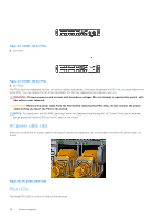
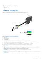
● Solid green-Input is OK. ● Flashing yellow-There is a fault with the PSU. ● Flashing green-System update. ● Off-PSU is off. DC power connections Each DC PSU comes with a connector cable. One cable is provided for each DC PSU. Figure 26. DC power connector and wiring block 1. Wiring block 2. Power connector 3. PSU connector 1. Strip a 1/2 inch section of insulation from each of the power connector's wires, as shown. 2. Insert each of the power connector's bare wire lengths into the wiring block. The blue wire is -48V, the black wire is the positive return, and the yellow/green wire is the ground wire, as shown. 3. Use a flat-blade screwdriver to tighten the screws that secures the bare wires into the wiring block. 4. Secure the site's DC power source wires to the other side of the wiring block, see steps 1 and 3. NOTE: Do not cross the wires. 5. Insert the DC power connector into the power socket of the DC PSU. Ensure that the connector pins firmly seat and you hear the click of the power connector's left and right levered clamps lock into place. NOTE: Never try to force the power connector into or out of the DC PSU power socket. NOTE: To remove the power connector from a DC PSU, unscrew the thumb screws and pull the power connector from the DC PSU socket. Power supplies 29
-
 1
1 -
2
-
3
-
4
-
5
-
6
-
7
-
8
-
9
-
10
-
11
-
12
-
13
-
14
-
15
-
16
-
17
-
18
-
19
-
20
-
21
-
22
-
23
-
 24
24 -
 25
25 -
 26
26 -
 27
27 -
 28
28 -
 29
29 -
 30
30 -
 31
31 -
 32
32 -
 33
33 -
 34
34 -
35
-
36
-
37
-
38
-
39
-
40
-
41
-
42
 |
 |
