Dell S5148F-ON EMC Networking OS10 Enterprise Edition Switch Configuration Gui - Page 29
S5148F-ON, VxRail node 1, VxRail node 2, VxRail node 4
 |
View all Dell S5148F-ON manuals
Add to My Manuals
Save this manual to your list of manuals |
Page 29 highlights
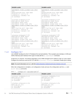
7.3 Configure switch interconnect - dual switch without VLT S5148F-Leaf1A S5148F-Leaf1B interface port-channel 127 description To_Leaf_1B switchport mode trunk switchport trunk allowed vlan 16111615 no shutdown interface port-channel 127 description To_Leaf_1A switchport mode trunk switchport trunk allowed vlan 16111615 no shutdown interface ethernet1/1/53 description To_Leaf_1B channel-group 127 mode active no shutdown interface ethernet1/1/53 description To_Leaf_1A channel-group 127 mode active no shutdown interface ethernet1/1/54 description To_Leaf_1B channel-group 127 mode active no shutdown interface ethernet1/1/54 description To_Leaf_1A channel-group 127 mode active no shutdown end write memory end write memory Single switch This example uses a four-node VxRail cluster connected to a single switch as shown below. S5148F-ON 1/1/23 21 19 17 18 20 22 24 VxRail node 1 VxRail node 2 VxRail node 3 25GbE connections Note: The jump box/DNS server, not shown, is connected to ports 1/1/9 and 1/1/10. VxRail node 4 Rack 1 Four-node cluster connected to a single switch The commands in the following sections are run to complete the switch configuration. The port numbers used in the configuration commands correspond to those shown in Figure 14. 29 Dell EMC Networking OS10 Enterprise Edition Switch Configuration Guide for VxRail 4.5
-
 1
1 -
2
-
3
-
4
-
5
-
6
-
7
-
8
-
9
-
10
-
11
-
12
-
13
-
14
-
15
-
16
-
17
-
18
-
19
-
20
-
21
-
22
-
23
-
 24
24 -
 25
25 -
 26
26 -
 27
27 -
 28
28 -
 29
29 -
 30
30 -
 31
31 -
 32
32 -
 33
33 -
 34
34 -
35
-
36
-
37
-
38
-
39
-
40
-
41
-
42
-
43
-
44
-
45
-
46
 |
 |
