Dell XPS 400 Owner's Manual - Page 66
NOTICE, Service Tag - no sound
 |
View all Dell XPS 400 manuals
Add to My Manuals
Save this manual to your list of manuals |
Page 66 highlights
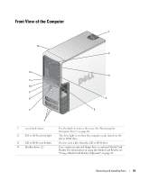
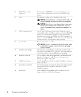
5 IEEE 1394 connector (optional) 6 vents 7 USB 2.0 connectors (2) 8 power button 9 hard-drive activity light 10 diagnostic lights (4) 11 headphone connector 12 microphone connector 13 Service Tag Use the optional IEEE 1394 connector for high-speed data devices such as digital video cameras and external storage devices. For adequate cooling, do not block any of the vents. NOTICE: Ensure that there is a minimum of two inches of space between all vents and any object near these vents. NOTICE: Keep the vent area clean and dust-free to ensure that the system is adequately ventilated. Use only a dry cloth to clean the vent area to avoid water damage to the system. Use the front USB connectors for devices that you connect occasionally, such as joysticks or cameras, or for bootable USB devices (see "System Setup Options" on page 116 for more information on booting to a USB device). It is recommended that you use the back USB connectors for devices that typically remain connected, such as printers and keyboards. Press to turn on the computer. NOTICE: To avoid losing data, do not use the power button to turn off the computer. Instead, perform an operating system shutdown. The hard drive activity light is on when the computer reads data from or writes data to the hard drive. The light might also be on when a device such as a CD player is operating. Use the lights to help you troubleshoot a computer problem based on the diagnostic code. For more information, see "Diagnostic Lights" on page 53. Use the headphone connector to attach headphones and most kinds of speakers. Use the microphone connector to attach a personal computer microphone for voice or musical input into a sound or telephony program. Used to identify your computer when you access the Dell Support website or call technical support. 66 Removing and Installing Parts
-
 1
1 -
2
-
3
-
4
-
5
-
6
-
7
-
8
-
9
-
10
-
11
-
12
-
13
-
14
-
15
-
16
-
17
-
18
-
19
-
20
-
21
-
22
-
23
-
24
-
25
-
26
-
27
-
28
-
29
-
30
-
31
-
32
-
33
-
34
-
35
-
36
-
37
-
38
-
39
-
40
-
41
-
42
-
43
-
44
-
45
-
46
-
47
-
48
-
49
-
50
-
51
-
52
-
53
-
54
-
55
-
56
-
57
-
58
-
59
-
60
-
 61
61 -
 62
62 -
 63
63 -
 64
64 -
 65
65 -
 66
66 -
 67
67 -
 68
68 -
 69
69 -
 70
70 -
 71
71 -
72
-
73
-
74
-
75
-
76
-
77
-
78
-
79
-
80
-
81
-
82
-
83
-
84
-
85
-
86
-
87
-
88
-
89
-
90
-
91
-
92
-
93
-
94
-
95
-
96
-
97
-
98
-
99
-
100
-
101
-
102
-
103
-
104
-
105
-
106
-
107
-
108
-
109
-
110
-
111
-
112
-
113
-
114
-
115
-
116
-
117
-
118
-
119
-
120
-
121
-
122
-
123
-
124
-
125
-
126
-
127
-
128
-
129
-
130
-
131
-
132
-
133
-
134
-
135
-
136
-
137
-
138
-
139
-
140
-
141
-
142
-
143
-
144
-
145
-
146
-
147
-
148
 |
 |
